WARP Project Forums - Wireless Open-Access Research Platform
You are not logged in.
#1 2014-Sep-11 03:55:53
- crimechb
- Member
- Registered: 2010-Sep-01
- Posts: 205
About WARP OFDM Reference Design
Dear Sir,
I would like to know the details of OFDM reference design.
Do you have reference paper list or all of the block algorithm method?
Offline
#2 2014-Sep-11 08:41:07
- murphpo
- Administrator
- From: Mango Communications
- Registered: 2006-Jul-03
- Posts: 5159
Re: About WARP OFDM Reference Design
We never wrote a paper detailing the block-by-block design of the OFDM ref design. Are the specific subsystems you're interested in?
Offline
#3 2014-Sep-11 22:52:12
- crimechb
- Member
- Registered: 2010-Sep-01
- Posts: 205
Re: About WARP OFDM Reference Design
Dear murphpo,
We would like to know the Packet Detection first .
Do you reference any paper or algorithm?
Offline
#4 2014-Sep-13 21:02:00
- murphpo
- Administrator
- From: Mango Communications
- Registered: 2006-Jul-03
- Posts: 5159
Re: About WARP OFDM Reference Design
The packet detection block is based on the scheme described by Schmidl & Cox. It uses an auto-correlator to search for the short training symbols in the preamble. The STS are periodic in 16 samples. The pkt detector searches for this periodicity and asserts when it finds a sequence with a large enough auto-correlation.
Offline
#5 2014-Sep-15 03:43:14
- crimechb
- Member
- Registered: 2010-Sep-01
- Posts: 205
Re: About WARP OFDM Reference Design
Dear murphpo,
Thanks.
Offline
#6 2014-Sep-29 03:49:45
- crimechb
- Member
- Registered: 2010-Sep-01
- Posts: 205
Re: About WARP OFDM Reference Design
Dear murphpo,
Thank you for your support.
We have finished the packet detection block.
We would like to know the Pilot Processing block.
Do you reference any paper or algorithm or book?
Best Regards,
Paul
Offline
#7 2014-Sep-29 11:03:44
- murphpo
- Administrator
- From: Mango Communications
- Registered: 2006-Jul-03
- Posts: 5159
Re: About WARP OFDM Reference Design
The PHY uses the pilot tones for phase error correction.
For each OFDM symbol the PHY calculates the phase of each pilot tone. These phases are first corrected by the estimated channel phases for the pilot subcarriers, then the phase estimates are averaged to calculate one phase error estimate per OFDM symbol. This per-symbol estimate is fed into the phase error tracking block, which is based on a scheme described in the literature (paper 1, paper 2). The output of the phase error tracking system is a single phase value per OFDM symbol. All subcarriers in the OFDM symbol are rotated by this phase error estimate before the symbol enters the equalizer.
Offline
#8 2014-Oct-21 23:31:14
- crimechb
- Member
- Registered: 2010-Sep-01
- Posts: 205
Re: About WARP OFDM Reference Design
Dear sir,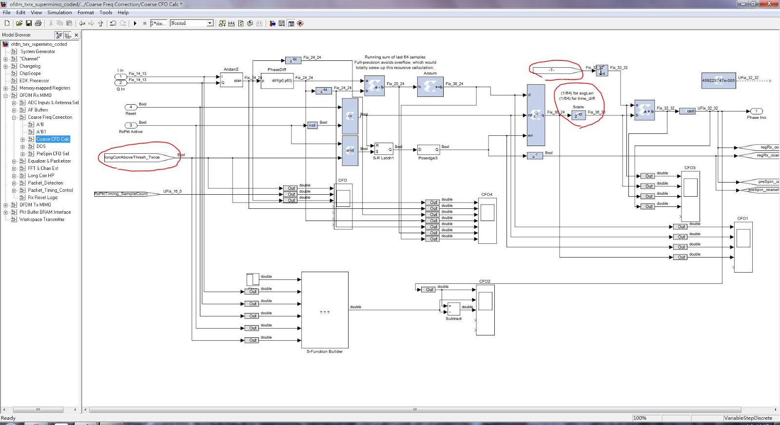
(1)In Coarse CFO Calc,The pin of "longCorrAboveThresh_Twice"is get the timing of frequency offset,But I don't know how to find the CFO,could you tell me?
(2)What's the avgLen and time_diff ?
(3)In CFO,The "-T-" is 2*10^-6,What is it mean?
Thanks.
Offline
#9 2014-Oct-22 19:56:57
- murphpo
- Administrator
- From: Mango Communications
- Registered: 2006-Jul-03
- Posts: 5159
Re: About WARP OFDM Reference Design
1) The CFO estimate is present at the "Phase Inc" (phase increment = frequency) port after the estimator runs. The estimator captures its result after the LTS correlator has fired the second time, hence the "longCorrAboveThresh_Twice" signal.
2) avgLen = 64, the number of frequency estimate samples that are summed. timeDiff = 64, the number of sample periods between each pair of samples whose phases are compared to estimate the phase difference, from which the frequency offset is estimated (phase change / time -> frequency)
3) This is a calibration value, left over from using the PHY for decode-and-forward experiments. The constant value there helps correct for a small CFO estimation error in the DF receive -> transmit processing. I would guess you can safely set that value to zero and see no effect in normal usage.
Offline
#10 2014-Oct-28 01:20:35
- crimechb
- Member
- Registered: 2010-Sep-01
- Posts: 205
Re: About WARP OFDM Reference Design
Dear murphpo,
Thank you for your support.
We would like to know the pilot phase error calc and CFO Calculation
Do you reference any paper or algorithm or book? 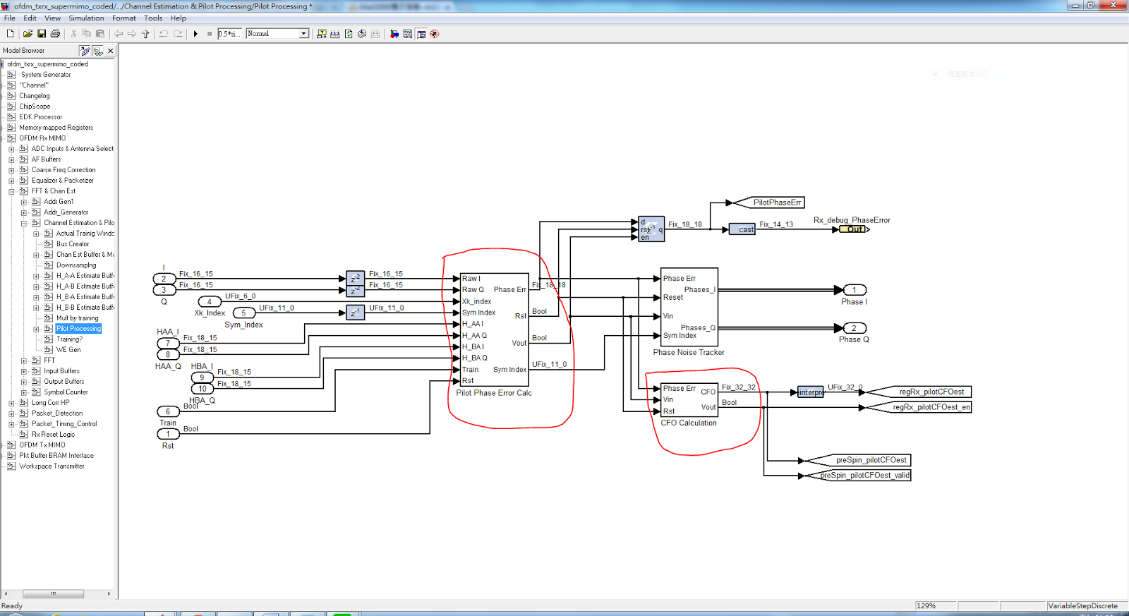
Best Regards,
Paul
Offline
#11 2014-Oct-28 22:58:44
- murphpo
- Administrator
- From: Mango Communications
- Registered: 2006-Jul-03
- Posts: 5159
Re: About WARP OFDM Reference Design
The phase error calc block extracts the pilot tones from each OFDM symbol and estimates the phase error of each pilot tone (vs. the known value for the pilot). The phase error estimates are averaged to generate a single phase error value per OFDM symbol. This value is fed into the phase noise tracking block. There are some URLs in the comments of that block for papers discussing a similar design.
That CFO calculation block is only used for decode-and-forward relaying. That block estimates the CFO using the phase error estimates in the last OFDM symbol, which represents the accumulated phase error resulting from residual CFO. This residual CFO estimate is added to the coarse CFO estimate (estimated from the LTS in the preamble). This opposite of this total CFO is then applied to the transmitted DF relay transmission, to mitigate the effects of independent transmitters (source + relay) with different carrier frequencies. This DF relay design is discussed in my thesis and related TVT paper.
Offline
#12 2014-Nov-04 23:44:36
- crimechb
- Member
- Registered: 2010-Sep-01
- Posts: 205
Re: About WARP OFDM Reference Design
Dear murphpo,
Thanks.
In Real-time Phase Tracking Method for IEEE 802.11 a/g/n Receiver under Phase Noise Condition ..
coarse tracking algorithm(1) 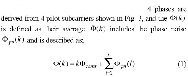
if algorithm(1)+ ,Can it replace the block of pilot phase error calculation?
The coarse tracking structure(red circle is algorithm(1)+ ):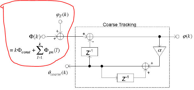
Offline
#13 2014-Nov-05 21:19:52
- murphpo
- Administrator
- From: Mango Communications
- Registered: 2006-Jul-03
- Posts: 5159
Re: About WARP OFDM Reference Design
It's been a long time since I studied that paper - I honestly don't recall the details well enough to suggest modifications to the algorithm.
To explore extensions/modification to the algorithm, I would strongly suggest implementing the algorithm in a MATLAB simulation and testing your ideas there.
The WARPLab SISO OFDM example would be a great place to start. This m script implements a simple OFDM Tx/Rx chain with waveform characteristics similar to the real-time PHY from the OFDM ref design.
This script implements a very simple pilot tone -> phase error correction system - the phase errors of the pilot tones in each OFDM symbol are averaged, then the whole OFDM symbol is de-rotated by that average error. The script implements no tracking algorithm across OFDM symbols. I would suggest extending the script with your phase tracking ideas and test performance with simulated noise + CFO.
Offline
#14 2014-Nov-16 23:48:40
- crimechb
- Member
- Registered: 2010-Sep-01
- Posts: 205
Re: About WARP OFDM Reference Design
Dear murphpo,
Do you know the CFO's tolerance range of OFDM reference design model ?
Last edited by crimechb (2014-Nov-16 23:51:32)
Offline
#15 2014-Nov-17 01:07:24
- murphpo
- Administrator
- From: Mango Communications
- Registered: 2006-Jul-03
- Posts: 5159
Re: About WARP OFDM Reference Design
The coarse CFO estimator range is 78kHz. This is due to the estimator using a phase difference across 64 samples. The phase must change by <pi (half cycle) in 64 sample periods. For 10MHz sampling in the OFDM ref design, this results in a 78kHz range (10MSps / (2*64 samples) = 78125Hz). On WARP hardware the actual CFO will be smaller than this, due to relatively tight tolerance on the TCXOs which drive the radio reference clocks.
Offline
#16 2014-Nov-17 06:44:58
- crimechb
- Member
- Registered: 2010-Sep-01
- Posts: 205
Re: About WARP OFDM Reference Design
Dear murphpo,
Thank you for your support.
Could you tell us the function of four blocks below?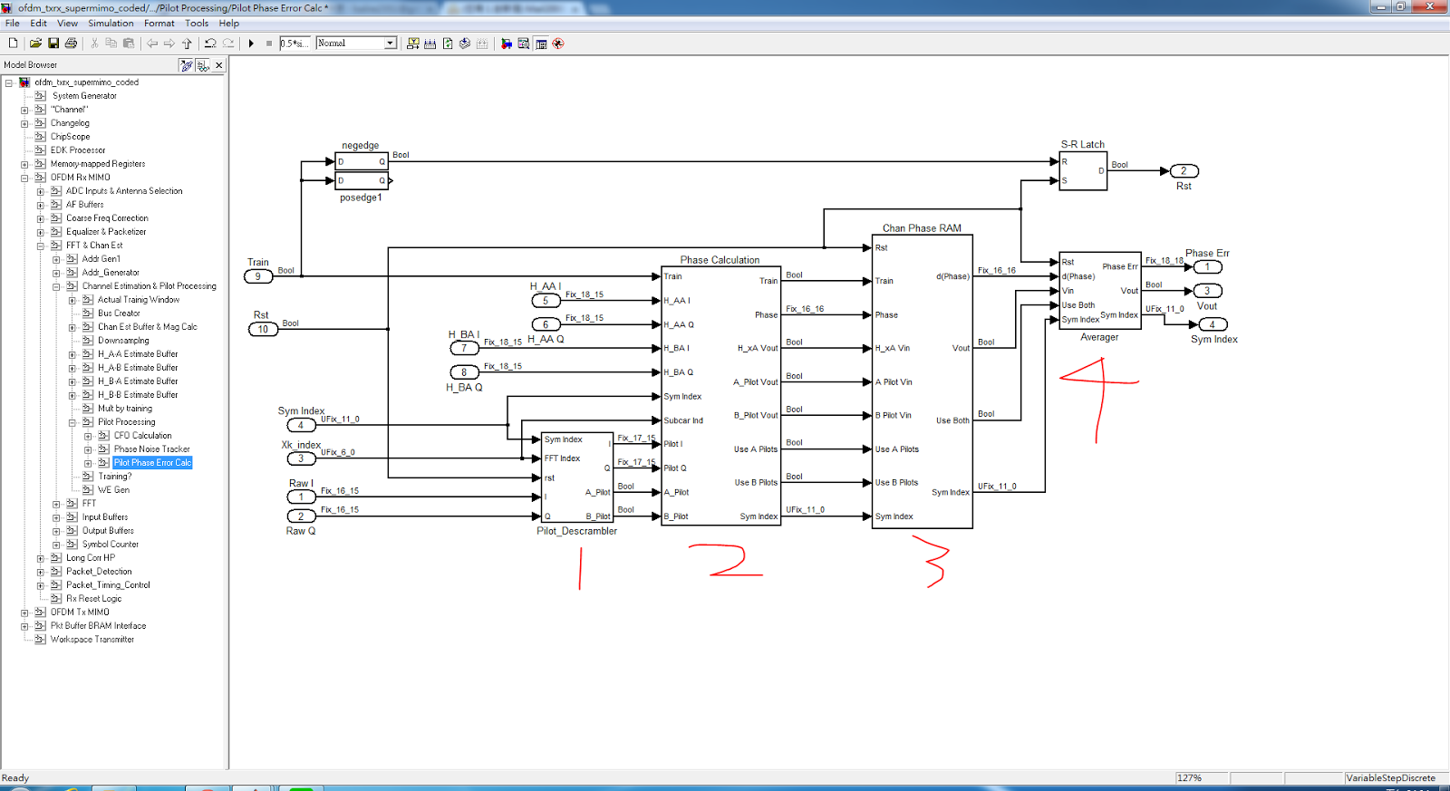
Offline
#17 2014-Nov-17 09:18:22
- murphpo
- Administrator
- From: Mango Communications
- Registered: 2006-Jul-03
- Posts: 5159
Re: About WARP OFDM Reference Design
1) The PHY uses a pseudo random sequence to negate the pilot tones across OFDM symbols (same as 802.11). This block unscrambles the pilot tones so that each tone has value +1*phase_error
2) This block calculates the phase of each unscrambled pilot tone. Any phase is a phase error.
3) This block stores the per-tone phase error for all pilot tones in each OFDM symbol, so they can be averaged in (4) and used to update the phase error tracking calculation.
Offline
#18 2014-Nov-17 21:36:13
- crimechb
- Member
- Registered: 2010-Sep-01
- Posts: 205
Re: About WARP OFDM Reference Design
Dear murphpo,
Thank you for your support.
In Averager block,it can select the Phase error by Multiplexer.
But we don't know the design concept.
Why it has two Accumulators and scale(0.5,0.25) and slice to four values .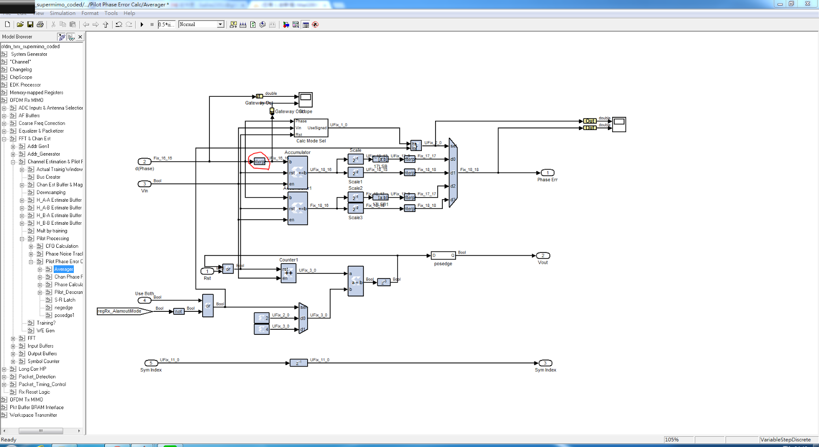
Last edited by crimechb (2014-Nov-17 21:47:49)
Offline
#19 2014-Nov-18 03:23:21
- murphpo
- Administrator
- From: Mango Communications
- Registered: 2006-Jul-03
- Posts: 5159
Re: About WARP OFDM Reference Design
The MSB of the mux select is controlled by logic that detects wrapping of phase values. For each OFDM symbol the unsigned or signed calculation will produce a valid average phase error, while the other will be invalid.
The LSB of the mux select is controlled by logic that decides how many pilot tones to use per OFDM symbol. In SISO and 2x2 MIMO modes 4 tones are used in every OFDM symbol. In Alamouti mode either 2 or 4 tones are used. Alamouti mode only uses 4 tones if the magnitude of all 4 pilot tone symbols are large enough, indicating the receiver observed energy from both Tx antennas. If the channel from one Tx antenna is too small only two pilot tones (the tones transmitted by the antenna with the stronger channel) are used.
Offline
#20 2014-Nov-18 22:17:05
- crimechb
- Member
- Registered: 2010-Sep-01
- Posts: 205
Re: About WARP OFDM Reference Design
Dear murphpo,
Thank you for your help.
1.Sorry,could you tell us why add the reinterpret ?
2.About model's Equalizer. It is using ZF.
We try to verify this Equalizer.
But our equation seems different with model.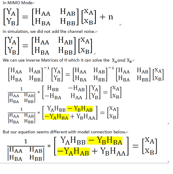
We try to use our equation as model's Equalizer. .
In the case of no channel noise, BER simulation results is wrong.
Is it our derivation error ? Do you have any suggestion?
Last edited by crimechb (2014-Nov-19 04:48:36)
Offline
#21 2014-Nov-19 14:23:07
- murphpo
- Administrator
- From: Mango Communications
- Registered: 2006-Jul-03
- Posts: 5159
Re: About WARP OFDM Reference Design
1.Sorry,could you tell us why add the reinterpret ?
That's part of the reinterpretation of the phase value when the unsigned arithmetic is used to handle wrapping in the signed version.
We try to use our equation as model's Equalizer. .
In the case of no channel noise, BER simulation results is wrong.
Is it our derivation error ? Do you have any suggestion?
Can you highlight where you see connections in the Rx PHY that look wrong? I just checked the model and it looks to me like the connections match the normal inverse expression you gave above (-Y_A*H_BA and -Y_B*H_AB).
Offline
#22 2014-Nov-19 21:33:14
- crimechb
- Member
- Registered: 2010-Sep-01
- Posts: 205
Re: About WARP OFDM Reference Design
We think that this OFDM model is solve the XA and red region is do YAHBB-YBHBA;solve the XB and red region is do -YAHAB+YBHAA.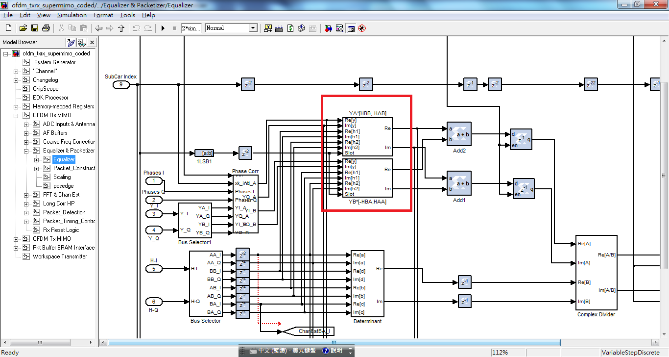
Offline
#23 2014-Nov-20 01:38:00
- murphpo
- Administrator
- From: Mango Communications
- Registered: 2006-Jul-03
- Posts: 5159
Re: About WARP OFDM Reference Design
Hmm. I agree that looks swapped - I mis-read the labels yesterday. My best guess is the labels are swapped relative to the actual values of the channel estimate signals. I'm out of the office for a few days so I can't confirm this. One way to check the logic would be to set the simulated channel matrix with unique values for the cross (BA, AB) terms and verify these values show up where you expect in the equalizer.
Offline
#24 2014-Nov-22 09:27:28
- crimechb
- Member
- Registered: 2010-Sep-01
- Posts: 205
Re: About WARP OFDM Reference Design
Dear murphpo,
Thanks you for your help.
We have two questions about H_A-A Estimate Buffer.
a. It's using LS algorithm.
Y=HX+n, if no noise, H=Y*(X Inverse Matrices).
Why the X value is always use +1. (Tx's training symbol)
We think that training symbol should has +1, -1 ,0 .
b.About input pin dina,Why it is Est_data+h[n].
In normal condition,The dina seems is Est_data.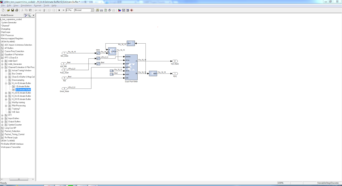
Offline
#25 2014-Nov-23 02:26:34
- murphpo
- Administrator
- From: Mango Communications
- Registered: 2006-Jul-03
- Posts: 5159
Re: About WARP OFDM Reference Design
The preamble contains two identical training symbols. The symbols are BPSK modulated values in the frequency domain. The "mult by training" block (up level up) multiplies the received training symbols by +1 or -1, converting each symbol into an estimate of the actual channel coefficient. The RAM above stores the first symbols estimates. Then when the second symbol arrives the first estimate is added to the second estimate for each subcarrier. This average estimate is then used by the equalizer.
Offline