WARP Project Forums - Wireless Open-Access Research Platform
You are not logged in.
#1 2015-Jan-27 09:37:35
- warpnewuser
- Member
- Registered: 2014-Jul-08
- Posts: 16
warplab hardware support higher receiver bandwidth?
Hi, I have a question about warp receiver higher bandwidth. I am using Warplab now.
For rx_lpf_corn_freq, it sets the corner frequency for the MAX2829 Rx path low pass filter. It seems that the largest bandwidth of Rx is 36 MHz. I found if I transmit 40 MHz signal, there was some subcarrier information missing.
My question is: Is there any latest hardware for WARP which can support 40 MHz signal, like: any daughter board?
Thanks!
Offline
#2 2015-Jan-27 22:17:11
- murphpo
- Administrator
- From: Mango Communications
- Registered: 2006-Jul-03
- Posts: 5159
Re: warplab hardware support higher receiver bandwidth?
It seems that the largest bandwidth of Rx is 36 MHz. I found if I transmit 40 MHz signal, there was some subcarrier information missing.
Can you provide more detail about the the waveform design, and your Rx PHY processing? I would expect the outermost subcarriers to be attenuated (these are typically empty in 40MHz 802.11 waveforms anyway), but not completely zeroed out.
Offline
#3 2015-Jan-28 04:40:37
- warpnewuser
- Member
- Registered: 2014-Jul-08
- Posts: 16
Re: warplab hardware support higher receiver bandwidth?
I would expect the outermost subcarriers to be attenuated (these are typically empty in 40MHz 802.11 waveforms anyway), but not completely zeroed out.
Yes, you are correct. They are not completely zeroed out, but has greatly attenuated. Because I need to convert the channel frequency response back to time domain, will these attenuated subcarriers have bad effect on time domain CIR result? If yes, how can I change the transmit signal to adapt to 36 MHZ channel and without attenuation on some subcarriers? or any latest hardware can support greater channel bandwidth like 40 Mhz?
Thanks for help!
Offline
#4 2015-Jan-28 11:05:27
- chunter
- Administrator
- From: Mango Communications
- Registered: 2006-Aug-24
- Posts: 1212
Re: warplab hardware support higher receiver bandwidth?
What do you mean by "greatly attenuated"? I ran a quick test using WARPLab to verify the Rx frequency response. With the Rx LPF set to its widest 36 MHz, here is the response I measured: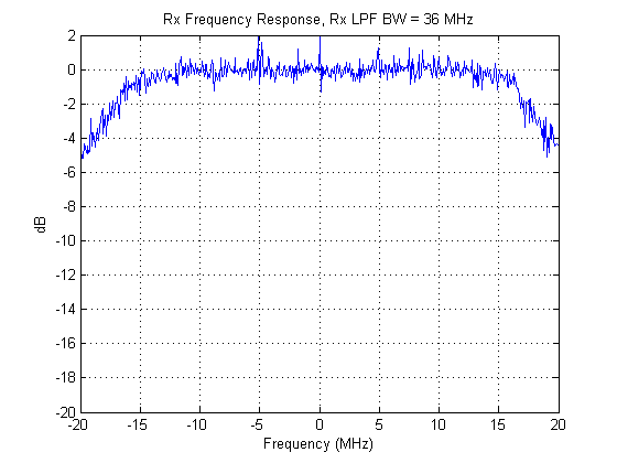
The -3dB points occur at ~-18 MHz and ~+18 MHz, confirming the BW is set to 36 MHz. Beyond that bandwidth, there is a little more attenuation with a worst-case attenuation of around 4 or 5 dB at the edge of the 40 MHz bandwidth. Overall, that is still a pretty flat response.
As murphpo said, even the 40 MHz mode of 802.11n/ac doesn't actually use the full 40 MHz. In OFDM systems the best way to adapt your transmission signal to a slightly narrower bandwidth is to disable the outermost subcarriers.
Offline
#5 2015-Feb-03 10:24:01
- warpnewuser
- Member
- Registered: 2014-Jul-08
- Posts: 16
Re: warplab hardware support higher receiver bandwidth?
Hi Chunter, thanks for the help!
Could you provide the details how you get this response? Like: what is the long training symbol you used for transmitting?
Offline
#6 2015-Feb-03 14:17:39
- chunter
- Administrator
- From: Mango Communications
- Registered: 2006-Aug-24
- Posts: 1212
Re: warplab hardware support higher receiver bandwidth?
There wasn't any kind of channel training to get that response. I sent wide-band noise through WARPLab and took an FFT of the received waveform. In the absence of any receive low-pass filter, this white noise would have a flat frequency response. The transmit vector was a complex Gaussian noise vector ( complex(randn(1,32768), randn(1,32768) ) that was scaled such that no sample exceeded +1 or -1.
Additionally, the transmitter has a maximum bandwidth as well. I wanted to make sure that the frequency response wasn't caused by attenuation at high frequencies on the Tx side. To do this, I actually swept the center channel of the transmitter relative to the receiver and took the maximum across those trials. Specifically, you are looking at the maximum frequency response magnitudes across the following trials: (tx chan, rx chan) = (4,6) , (5,6) , (6,6) , (7,6) , (8,6)
Offline
#7 2015-Apr-28 06:15:27
- warpnewuser
- Member
- Registered: 2014-Jul-08
- Posts: 16
Re: warplab hardware support higher receiver bandwidth?
Hi Chunter,
Thanks for your detailed explanation! I have tried to repeat your experiment to measure the Rx A frequency reponse by sending wideband noise (using wire).
Some codes are as below:
wl_interfaceCmd(nodes,'RF_ALL','tx_lpf_corn_freq',2); %Configure Tx for 36MHz of bandwidth %--------Configure Tx LPF
wl_interfaceCmd(nodes,'RF_ALL','rx_lpf_corn_freq',3); %Configure Rx for 36MHz of bandwidth %--------Configure Rx LPF
txData=complex(randn(1,32768), randn(1,32768)); %-----Transmit nosie vector
magTransform=20*log10(abs(fft(rx_IQ(1000:1127,1)))./max(abs(fft(rx_IQ(1000:1127,1))))); %-------Compute signal power in DB using 128 samples.
The below first figure is the result I got, it's different from the figure your showed. I don't know the reason why I can't get the similar result as you had. Is there anything wrong with above code?
Below two figures are frequency response results by sending long training symbol.
T_long =[ 0,0,0,0,0,0,1,1,-1,-1,1,1,-1,1,-1,1,1,1,1,1,1,-1,-1,1,1,-1,1,-1,1,1,1,1,1,...
1, -1, -1, 1, 1, -1, 1, -1, 1, -1, -1, -1, -1, -1, 1, 1, -1, -1, 1, -1, 1, -1, 1, 1, 1, 1, 1,...
-1,1,-1,1,1,-1,1,1,1,-1,-1,...
1, 1, -1, -1, 1, 1, -1, 1, -1, 1, 1, 1, 1, 1, 1, -1, -1, 1, 1, -1, 1, -1, 1, 1, 1, 1,...
1,-1,-1,1,1,-1,1,-1,1,-1,-1,-1,-1,-1,1,1,-1,-1,1,-1,1,-1,1,1,1,1,0,0,0,0,0]; %--This is not a standard LTS, just used to see frequency response , total 128 subcarriers.
This figure is result of magnitude frequency response (using fftshift, so the empty subcarriers now in the middle) in DB. Y axis---Magnitude (in DB), X axis---subcarriers. From the result, I can see that from subcarrier 26 to subcarrier 100, it's about the flat fading, but for subcarriers beyond this, it has antenuatted a lot. I expected to see the flat fading since I use wire to transmit. 
Also, the below figure is the phase difference between RFA and RFD, RFB and RFD, RFC and RFD across subcarriers except those empty subcarriers. So now total subcarrier is 117. Y axis---Angle (in rad), X axis---subcarriers. What is strange here is that: the result of subcarrier 1 to subcarrier 25, subcarrier 90 to subcarrier 117 has very large fluctuation (And if I run many times, these results change with time (sometime, the change is large; sometimes, it's small)). While for subcarriers from 40 to 80, the results has little fluctuation and almost doesn't change with time . Is it possible that this is caused by Rx LPF (Although I have set it to be 36Mhz)? Because I need to calibrate the phase difference for all the subcarriers, these fluctuated results make me very difficult to calibrate. 
pls help..
Offline
#8 2015-Apr-28 09:39:33
- chunter
- Administrator
- From: Mango Communications
- Registered: 2006-Aug-24
- Posts: 1212
Re: warplab hardware support higher receiver bandwidth?
warpnewuser wrote:
Thanks for your detailed explanation! I have tried to repeat your experiment to measure the Rx A frequency reponse by sending wideband noise (using wire).
Some codes are as below:
wl_interfaceCmd(nodes,'RF_ALL','tx_lpf_corn_freq',2); %Configure Tx for 36MHz of bandwidth %--------Configure Tx LPF
wl_interfaceCmd(nodes,'RF_ALL','rx_lpf_corn_freq',3); %Configure Rx for 36MHz of bandwidth %--------Configure Rx LPF
txData=complex(randn(1,32768), randn(1,32768)); %-----Transmit nosie vector
magTransform=20*log10(abs(fft(rx_IQ(1000:1127,1)))./max(abs(fft(rx_IQ(1000:1127,1))))); %-------Compute signal power in DB using 128 samples.
The below first figure is the result I got, it's different from the figure your showed. I don't know the reason why I can't get the similar result as you had. Is there anything wrong with above code?
Couple of things:
- txData in your above code will almost certainly have I and Q values that exceed the range of [-1,1]. WARPLab should produce a warning if you try to send that and then clip any samples outside of that range down to that range. I'm not sure what the spectrum of clipped Gaussian noise looks like (easy to check in MATLAB).
- The FFT of a specific white noise vector isn't frequency flat. In fact, the FFT of a Gaussian white noise vector is itself a Gaussian white noise vector. The average across many different vectors will be flat. My previous plot averaged across multiple trials to get it to look flat.
- Given that any given reception isn't going to have a flat response after the FFT, you can't normalize by the maximum value of that particular FFT. Do your normalization after you do your averaging.
- Why are you only truncating to 128 samples and ignoring the other 32640 samples? It makes sense to slice out the beginning and end of time stuff (where the transmitter just turns on or off). But I'd increase the width of the slice considerably to improve your frequency resolution.
warpnewuser wrote:
Below two figures are frequency response results by sending long training symbol.
T_long =[ 0,0,0,0,0,0,1,1,-1,-1,1,1,-1,1,-1,1,1,1,1,1,1,-1,-1,1,1,-1,1,-1,1,1,1,1,1,...
1, -1, -1, 1, 1, -1, 1, -1, 1, -1, -1, -1, -1, -1, 1, 1, -1, -1, 1, -1, 1, -1, 1, 1, 1, 1, 1,...
-1,1,-1,1,1,-1,1,1,1,-1,-1,...
1, 1, -1, -1, 1, 1, -1, 1, -1, 1, 1, 1, 1, 1, 1, -1, -1, 1, 1, -1, 1, -1, 1, 1, 1, 1,...
1,-1,-1,1,1,-1,1,-1,1,-1,-1,-1,-1,-1,1,1,-1,-1,1,-1,1,-1,1,1,1,1,0,0,0,0,0]; %--This is not a standard LTS, just used to see frequency response , total 128 subcarriers.
This figure is result of magnitude frequency response (using fftshift, so the empty subcarriers now in the middle) in DB. Y axis---Magnitude (in DB), X axis---subcarriers. From the result, I can see that from subcarrier 26 to subcarrier 100, it's about the flat fading, but for subcarriers beyond this, it has antenuatted a lot. I expected to see the flat fading since I use wire to transmit.
Also, the below figure is the phase difference between RFA and RFD, RFB and RFD, RFC and RFD across subcarriers except those empty subcarriers. So now total subcarrier is 117. Y axis---Angle (in rad), X axis---subcarriers. What is strange here is that: the result of subcarrier 1 to subcarrier 25, subcarrier 90 to subcarrier 117 has very large fluctuation (And if I run many times, these results change with time (sometime, the change is large; sometimes, it's small)). While for subcarriers from 40 to 80, the results has little fluctuation and almost doesn't change with time . Is it possible that this is caused by Rx LPF (Although I have set it to be 36Mhz)? Because I need to calibrate the phase difference for all the subcarriers, these fluctuated results make me very difficult to calibrate.
pls help..
Can you describe your setup in more detail? What is each interface doing exactly? Are they all simultaneously receiving a single-antenna transmission? Are these 4 sequential experiments with results overlaid in a plot? Assuming its the latter, are you doing anything to synchronize your TX and RX start times like using the CM-MMCX clock module? If not, Ethernet jitter on the trigger packet will cause relative random delays between the RF paths. Those temporal delays will manifest as a frequency-dependent phase shift like what you are seeing.
Offline
#9 2015-Apr-28 12:36:36
- warpnewuser
- Member
- Registered: 2014-Jul-08
- Posts: 16
Re: warplab hardware support higher receiver bandwidth?
chunter wrote:
Couple of things:
- txData in your above code will almost certainly have I and Q values that exceed the range of [-1,1]. WARPLab should produce a warning if you try to send that and then clip any samples outside of that range down to that range. I'm not sure what the spectrum of clipped Gaussian noise looks like (easy to check in MATLAB).
- The FFT of a specific white noise vector isn't frequency flat. In fact, the FFT of a Gaussian white noise vector is itself a Gaussian white noise vector. The average across many different vectors will be flat. My previous plot averaged across multiple trials to get it to look flat.
- Given that any given reception isn't going to have a flat response after the FFT, you can't normalize by the maximum value of that particular FFT. Do your normalization after you do your averaging.
- Why are you only truncating to 128 samples and ignoring the other 32640 samples? It makes sense to slice out the beginning and end of time stuff (where the transmitter just turns on or off). But I'd increase the width of the slice considerably to improve your frequency resolution.
Okay, I will modify the code and report back the result.
chunter wrote:
Can you describe your setup in more detail? What is each interface doing exactly? Are they all simultaneously receiving a single-antenna transmission? Are these 4 sequential experiments with results overlaid in a plot? Assuming its the latter, are you doing anything to synchronize your TX and RX start times like using the CM-MMCX clock module? If not, Ethernet jitter on the trigger packet will cause relative random delays between the RF paths. Those temporal delays will manifest as a frequency-dependent phase shift like what you are seeing.
The setup is: I use one warp node RFA to transmit signal use a wire which is attached to a one to four splitter, then each of four out port is attached to the second warp node RFA,RFB,RFC and RFD through equal length wires. So these four Rx sharing the same clock signal. After RFA, RFB, RFC and RFD have received signal, I calculated the channel frequency response for each RF.
This figure is the magnitude for each RF across all the subcarriers (Y axis---Magnitude (in DB), X axis---subcarriers):
This figure is the phase difference of RFA and RFD, RFB and RFD, RFC and RFD. (RFD is the reference radio)
The code to calculate of RFA and RFD phase diff is:
phasediff=fftshift(mod((angle(RFA))-(angle(RFD))+pi,2*pi)-pi))
The result is (Y axis---Angle (in rad), X axis---subcarriersis):
The problem is: if I run this experiment 10 times, the phase difference from subcarrier 1 to subcarrier 25, subcarrier 90 to subcarrier 117 changes every time, while for subcarriers from 40 to 80, the results almost doesn't change. Since I didn't reset the PLL of each RF, the phase difference across the subcarriers shouldn't change with time. This is true for subcarriers from 40 to 80. While for others, it's not.
Any possible reason?
Offline
#10 2015-Apr-28 13:15:30
- murphpo
- Administrator
- From: Mango Communications
- Registered: 2006-Jul-03
- Posts: 5159
Re: warplab hardware support higher receiver bandwidth?
What version of WARPLab are you using?
Offline
#11 2015-Apr-29 05:29:40
- warpnewuser
- Member
- Registered: 2014-Jul-08
- Posts: 16
Re: warplab hardware support higher receiver bandwidth?
murphpo wrote:
What version of WARPLab are you using?
I am using WARPLAB 7.3.0.
Offline
#12 2015-Apr-29 08:59:03
- chunter
- Administrator
- From: Mango Communications
- Registered: 2006-Aug-24
- Posts: 1212
Re: warplab hardware support higher receiver bandwidth?
I'd suggest moving to the latest WARPLab 7.5.1 and re-running your experiment. Your existing code should just work with the new bitstream, but its likely that your current code uses some of the older script conventions and will produce warnings in the MATLAB console. You can find details on these new script conventions on this page.
In one of your previous replies, you stated that you were using a Tx LPF setting of 2. You should open that up all the way to 3. Currently, you are actually doubly attenuating the outermost subcarriers since they are going through the transition region of the passband on both the Tx and Rx LPFs. In my earlier noise-based spectrum plot, I had the Tx LPF set to 3 to make sure that the only attenuation I was seeing was caused by the Rx.
Offline
#13 2015-Apr-29 09:01:21
- murphpo
- Administrator
- From: Mango Communications
- Registered: 2006-Jul-03
- Posts: 5159
Re: warplab hardware support higher receiver bandwidth?
I'll second the recommendation of updating to WL 7.5.1. There have been many bug fixes and performance improvements since 7.3. The core API has not changed (i.e. your scripts should work without modification).
Offline