WARP Project Forums - Wireless Open-Access Research Platform
You are not logged in.
#26 2014-Nov-24 02:53:14
- crimechb
- Member
- Registered: 2010-Sep-01
- Posts: 205
Re: About WARP OFDM Reference Design
Dear murphpo,
Thanks you for your help.
We have one question about Chan Phase Ram block:
This block take out the phase of four pilots by RAM.
Why use the addsub block and let the input signal minus the pilot's phase? (We think just output signal to Averager block without this addsub block )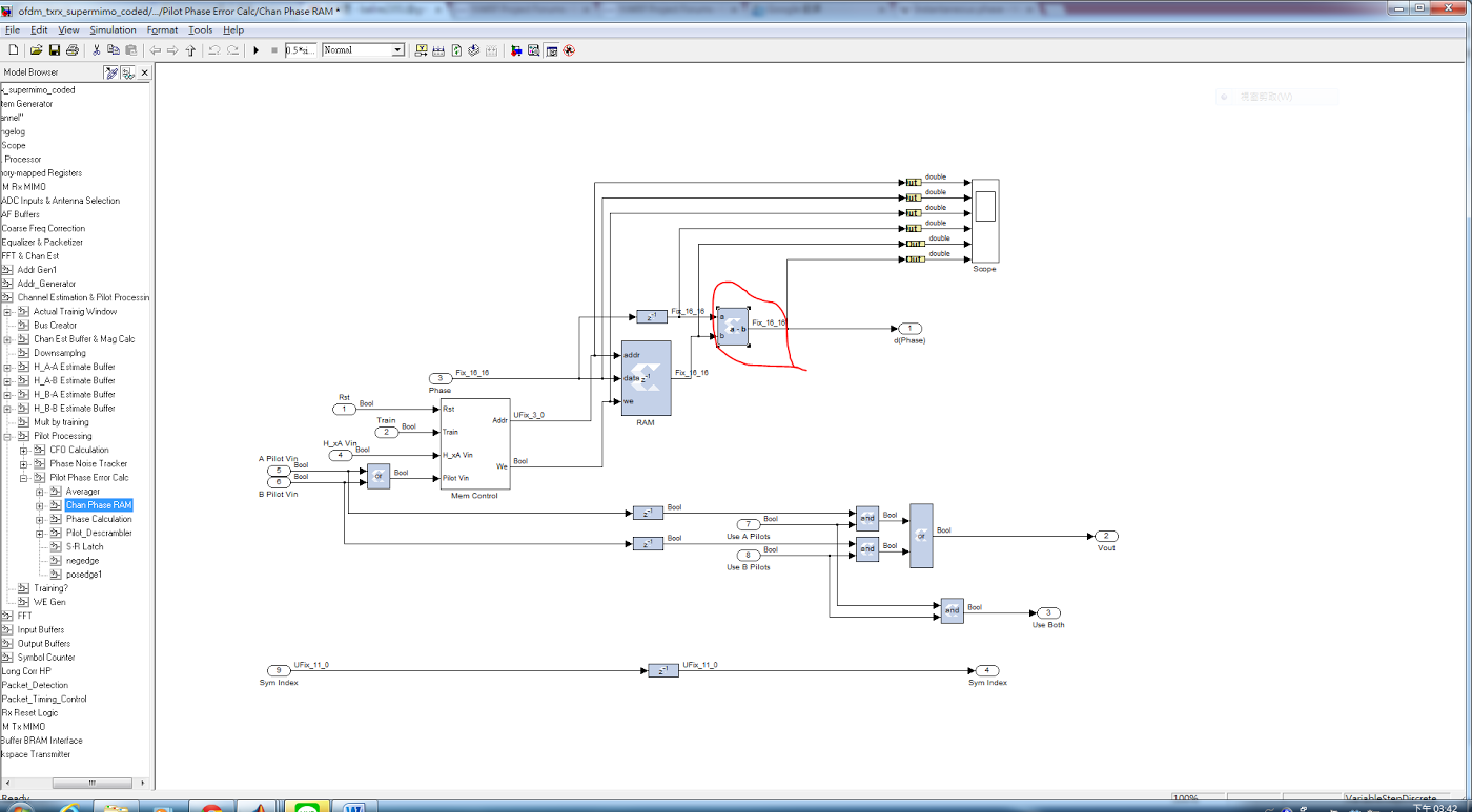
Offline
#27 2014-Nov-24 08:50:51
- murphpo
- Administrator
- From: Mango Communications
- Registered: 2006-Jul-03
- Posts: 5159
Re: About WARP OFDM Reference Design
The RAM contains the phase values of the channel estimates. The subtraction computes the phase error of each received pilot tone, as the actual phase of the received pilot minus the phase of the pilot subcarrier's channel estimate.
Offline
#28 2014-Nov-27 08:41:24
- crimechb
- Member
- Registered: 2010-Sep-01
- Posts: 205
Re: About WARP OFDM Reference Design
Dear murphpo,
Thanks for your help.
A.
murphpo wrote:
Hmm. I agree that looks swapped - I mis-read the labels yesterday. My best guess is the labels are swapped relative to the actual values of the channel estimate signals. I'm out of the office for a few days so I can't confirm this. One way to check the logic would be to set the simulated channel matrix with unique values for the cross (BA, AB) terms and verify these values show up where you expect in the equalizer.
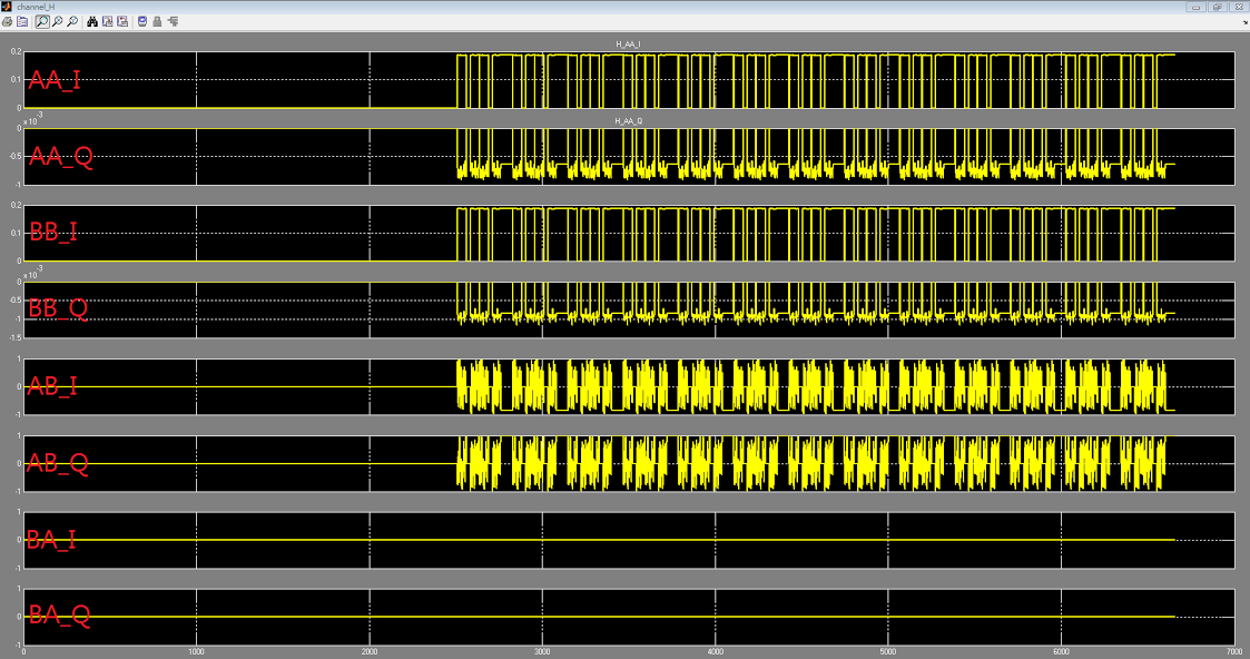
We have test the connection of HBA and HBA.
1. Change the AB's interference.
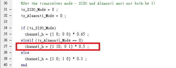
2. Check the model's scope .
The connection of AB and BA ,the model is opposite to theory algorithm.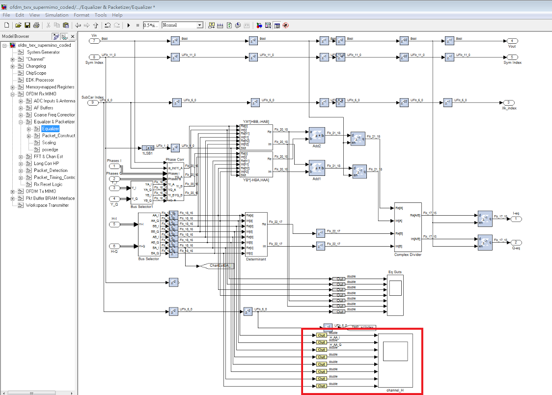
Last edited by crimechb (2014-Dec-02 01:06:27)
Offline
#29 2014-Dec-02 01:06:39
- crimechb
- Member
- Registered: 2010-Sep-01
- Posts: 205
Re: About WARP OFDM Reference Design
B. About phase error calc block.
murphpo wrote:
The phase error calc block extracts the pilot tones from each OFDM symbol and estimates the phase error of each pilot tone (vs. the known value for the pilot). The phase error estimates are averaged to generate a single phase error value per OFDM symbol. This value is fed into the phase noise tracking block
Do you mean the ofdm symbol have"one"phase error value?
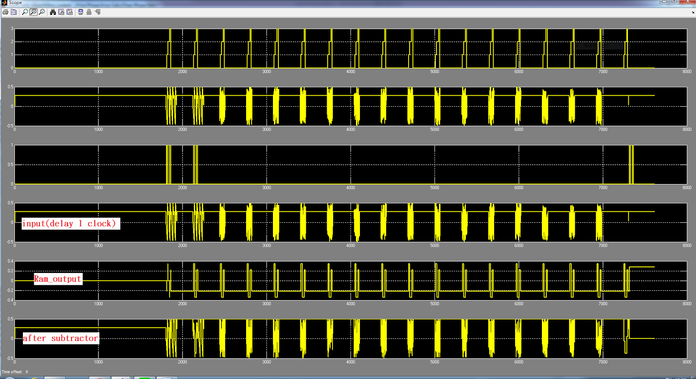
We have check the output waveform.
In the waveform,we use the four pilots calculate the avg. value and the phase error has four values.
We think it seems segmented concept.
ex.One ofdm symbol has 64 sub-carriers,and pilot location are 8 、22、44、58,and 1 sub-carrier~8 sub-carrier has one phase error value... 9 sub-carrier~22 sub-carrier has phase error value ....etc
Is it correct?
Offline
#30 2014-Dec-02 09:50:06
- murphpo
- Administrator
- From: Mango Communications
- Registered: 2006-Jul-03
- Posts: 5159
Re: About WARP OFDM Reference Design
Each OFDM symbol has 4 pilot tones. The phase error block calculates the phase of each pilot tone. These 4 phases are averaged to generate a single phase error estimate for that OFDM symbol.
Offline
#31 2014-Dec-02 21:55:36
- balire2351
- Member
- Registered: 2014-Nov-20
- Posts: 19
Re: About WARP OFDM Reference Design
dear murphpo:
about post#29,
In the waveform,we use the four pilots calculate the avg. value and the phase error has four values.
We think it seems segmented concept.
ex.One ofdm symbol has 64 sub-carriers,and pilot location are 8 、22、44、58,and 1 sub-carrier~8 sub-carrier has one phase error value... 9 sub-carrier~22 sub-carrier has phase error value ....etc
Is it correct?
Offline
#32 2014-Dec-03 05:18:46
- crimechb
- Member
- Registered: 2010-Sep-01
- Posts: 205
Re: About WARP OFDM Reference Design
Dear murphpo,
1.Use the pilot phase error calc block which it can get the phase error value.
Why this model can not use this value to compensate the phase error.
2.Why this model need to add the phase noise tracker block to compensate the phase error?
Offline
#33 2014-Dec-04 10:14:39
- murphpo
- Administrator
- From: Mango Communications
- Registered: 2006-Jul-03
- Posts: 5159
Re: About WARP OFDM Reference Design
In the waveform,we use the four pilots calculate the avg. value and the phase error has four values.
We think it seems segmented concept.
ex.One ofdm symbol has 64 sub-carriers,and pilot location are 8 、22、44、58,and 1 sub-carrier~8 sub-carrier has one phase error value... 9 sub-carrier~22 sub-carrier has phase error value ....etc
Is it correct?
The PHY uses the pilot tones to estimate and correct phase error due to residual CFO (CFO left after the time-domain coarse CFO estimation+correction has been applied). Residual CFO manifests in the frequency domain as a phase offset which is constant across subcarriers in each OFDM symbol and increases with each OFDM symbol. Because the phase error due to CFO is equal across subcarriers, the phases of the 4 pilot tones are averaged to compute a single phase error estimate. The resulting phase error correction applies a single phase value to all subcarriers in each OFDM symbol.
1.Use the pilot phase error calc block which it can get the phase error value.
Why this model can not use this value to compensate the phase error.
2.Why this model need to add the phase noise tracker block to compensate the phase error?
The phase error tracking system is not strictly required, but will improve performance in situations where noise may degrade the phase estimates extracted from the pilot tones. The "Real-time Phase Tracking" papers we discussed above describe this in detail.
Offline
#34 2015-May-30 09:09:47
- crimechb
- Member
- Registered: 2010-Sep-01
- Posts: 205
Re: About WARP OFDM Reference Design
Dear murphpo,
If RX error dropped the Ethernet packets then ResetRX =1. Is it correct?
https://www.dropbox.com/s/mviz9qxqg6uwg … g.png?dl=0
When we simulate the OFDM referncee design .
regRx_BER_Errors=0 and ResetRX =1 .
What 's the situation?
Offline
#35 2015-Jun-01 10:22:38
- murphpo
- Administrator
- From: Mango Communications
- Registered: 2006-Jul-03
- Posts: 5159
Re: About WARP OFDM Reference Design
That ResetRx signal will assert when the PHY detects an error in the received header (CRC fails) or if header indicates an invalid packet length (good CRC, but invalid LENGTH field). When the ResetRx signal asserts the PHY pipeline is flushed immediately - the PHY does not attempt to decode the payload, because it does not know what rate/length values to use. In this case there are no decoded bits for the BER counters to track. A bad header does not mean zero BER. It means no bits at all. BER is not a sufficient metric for characterizing a packet-based system. BER should be considered along with PER.
Offline
#36 2015-Jun-04 04:53:00
- crimechb
- Member
- Registered: 2010-Sep-01
- Posts: 205
Re: About WARP OFDM Reference Design
Dear murphpo,
Thanks for your help.
We would like to change the reference design's Zero-Forcing equalizer .
Now our equalizer algorithm's output is almost +-20.
If we still want to use FEC_Decoder of Soft_Decoding.
Does we need to normalized our equalizer algorithm output to original output range of Zreo-Forcing equalizer ?
Do you know the ideal positive and negative peak range of FEC_Decoder input (rx_i, rx_q) ?
Offline
#37 2015-Jun-04 09:40:00
- murphpo
- Administrator
- From: Mango Communications
- Registered: 2006-Jul-03
- Posts: 5159
Re: About WARP OFDM Reference Design
Does we need to normalized our equalizer algorithm output to original output range of Zreo-Forcing equalizer ?
Yes- in the OFDM Reference Design Rx PHY the decoder black box also implements the de-mapping from modulated symbols to soft bits. The rx_i/rx_q inputs to the decoder black box should be equalized symbols with (ideally) the same values as symbols from the transmitted constellation. If your equalizer introduces a constant scaling vs. the transmitted symbols, you should remove this scaling from the signals before the decoder. Alternatively you could modify the decoder Verilog to shift the decision boundaries to match your scaled constellation.
Offline