802.11 Reference Design
- Download
- Changelog
- FAQ
- Architecture
Using the Design
Benchmarks
- IFS Calibration
- Throughput
- Transmitter Characterization
- Receiver Characterization
- Pkt. Det. Min. Power Characterization
MAC
Upper-level
Lower-level
- PHY
Experiments Framework
- Packet Flow
- FPGA Architecture
- FPGA Resource Usage
- App Notes
- Other Resources
- License
- Changelog
802.11 Reference Design App Note: FDD NoMAC
This application note presents an extension of the 802.11 Reference Design to support frequency-division duplexing. This extension supports the AP and STA applications for CPU High and a custom FDD-capable NoMAC in CPU Low (note 1). The design uses both RF interfaces on two WARP v3 nodes. The RF A and B interfaces are tuned to different channels, and traffic flows in different directions at each interface, as illustrated below.
----------                 -----------
    RF A | >-- 2.4 GHz --> | RF A
AP       |                 |       STA
    RF B | <--  5 GHz  --< | RF B
----------                 -----------
This app note requires 802.11 Reference Design version 1.6.1 or newer (the lower MAC framework in previous designs did not support the two-step Rx processing flow required for this extension).
C Code Changes
Extending the 802.11 Reference Design to support FDD requires only C code changes. There are 3 stages of code modifications required:
- Update the high MAC (AP & STA) to use different RF interfaces for Tx and Rx
- Update the lower MAC framework to:
- Tune the RF A and B interfaces to different channels
- Configure the Rx RF interface to stay active during Tx
- Disable logic paths that block simultaneous Tx/Rx PHY events
- Update the NoMAC application to handle simultaneous Tx/Rx
1. AP & STA Changes
The upper and lower MAC frameworks already support setting different antennas for Tx and Rx. By default each high MAC application sets the Tx and Rx antennas at boot using the selections defined in the top-level macros named WLAN_DEFAULT_TX_ANTENNA and WLAN_DEFAULT_RX_ANTENNA. For this 2-node FDD link we must update the AP and STA to use opposite antennas for Tx and Rx.
At the top of wlan_mac_ap.c and wlan_mac_sta.c, modify the existing macros to:
AP:
// Tx on RF A, Rx on RF B
#define  WLAN_DEFAULT_TX_ANTENNA  TX_ANTMODE_SISO_ANTA
#define  WLAN_DEFAULT_RX_ANTENNA  RX_ANTMODE_SISO_ANTB
STA:
// Rx on RF A, Tx on RF B
#define  WLAN_DEFAULT_TX_ANTENNA  TX_ANTMODE_SISO_ANTB
#define  WLAN_DEFAULT_RX_ANTENNA  RX_ANTMODE_SISO_ANTA
2. MAC Low Framework Changes
The lower MAC framework manages control of the MAC and PHY cores and the circuits in the RF interfaces. In the reference code the framework enables protection signals between the Tx PHY, Rx PHY and MAC cores that automatically reset the Rx PHY whenever the Tx PHY is active. These signals guarantee the node never receives its own transmissions, either through leakage from the Tx to Rx analog circuits on one interface or between RF interfaces when both are enabled. The lower framework also tunes both RF interfaces to the same center frequency whenever the MAC application requests a different channel.
Tx/Rx PHY Interlock
The PHY-level mutual-exclusion between Tx and Rx is enabled in two configuration registers, one in the Rx PHY, the other in the MAC core. To disable the interlock:
In wlan_phy_util.c modify the wlan_phy_init() function:
// Config bit WLAN_RX_REG_CFG_USE_TX_SIG_BLOCK holds Rx PHY inputs at 0 when Tx PHY is active
//  Reference code sets this bit - must be disabled for FDD
// REG_SET_BITS(WLAN_RX_REG_CFG, WLAN_RX_REG_CFG_USE_TX_SIG_BLOCK); // ref code
REG_CLEAR_BITS(WLAN_RX_REG_CFG, WLAN_RX_REG_CFG_USE_TX_SIG_BLOCK);
In wlan_mac_low.c modify the wlan_mac_hw_init() function:
// Config bit WLAN_MAC_CTRL_MASK_BLOCK_RX_ON_TX blocks Rx pkt detection events when MAC core
//  TX_PHY_ACTIVE latch is active - must be disabled for FDD
// REG_SET_BITS(WLAN_MAC_REG_CONTROL, WLAN_MAC_CTRL_MASK_BLOCK_RX_ON_TX); //ref code
REG_CLEAR_BITS(WLAN_MAC_REG_CONTROL, WLAN_MAC_CTRL_MASK_BLOCK_RX_ON_TX);
Keep Rx RF Interface Enabled
The reference code disables the Rx circuits on every RF interface when any interface is currently transmitting. For FDD the Rx interface must be configued to say in Rx mode independent of the Tx state of another interface. This is achieved by modifying the framework's wlan_rx_config_ant_mode() function in wlan_phy_util.c. Changes are required to 5 lines (add 3 lines, comment-out 2 lines), identified by the inline comments below:
...
    // Disable PHY control of all RF interfaces - selected interfaces to re-enabled below
    radio_controller_setCtrlSource(RC_BASEADDR, RC_ALL_RF, RC_REG0_RXEN_CTRLSRC, RC_CTRLSRC_REG);

    // Disable all RF interfaces that are already software-controlled
    radio_controller_TxRxDisable(RC_BASEADDR, RC_ALL_RF); // FDD-NoMAC

    switch (ant_mode) {
        case RX_ANTMODE_SISO_ANTA:
            REG_SET_BITS(WLAN_RX_REG_CFG, WLAN_RX_REG_CFG_PKT_DET_EN_ANT_A);
            wlan_phy_select_rx_antenna(RX_ANTMODE_SISO_ANTA);
            //radio_controller_setCtrlSource(RC_BASEADDR, RC_RFA, RC_REG0_RXEN_CTRLSRC, RC_CTRLSRC_HW); // ref code
            radio_controller_RxEnable(RC_BASEADDR, RC_RFA); // FDD-NoMAC
            wlan_agc_config(RX_ANTMODE_SISO_ANTA);
        break;

        case RX_ANTMODE_SISO_ANTB:
            REG_SET_BITS(WLAN_RX_REG_CFG, WLAN_RX_REG_CFG_PKT_DET_EN_ANT_B);
            wlan_phy_select_rx_antenna(RX_ANTMODE_SISO_ANTB);
            //radio_controller_setCtrlSource(RC_BASEADDR, RC_RFB, RC_REG0_RXEN_CTRLSRC, RC_CTRLSRC_HW); // ref code
            radio_controller_RxEnable(RC_BASEADDR, RC_RFB); // FDD-NoMAC
            wlan_agc_config(RX_ANTMODE_SISO_ANTB);
        break;
   ...
Different Channels on RF A/B
The reference code tunes all RF interfaces to the same center frequency any time the MAC application requests a new channel. The RF interfaces are tuned in the wlan_mac_low_set_radio_channel(u32 channel) function in wlan_mac_low.c. The channel argument is an 802.11 channel index. This function also enables/disables the Rx PHY DSSS receiver when tuned to a 5 GHz channel, as DSSS transmissions only occur in 2.4 GHz channels.
A fully-general FDD implementation would modify this function to support a channel argument per RF interface. However this app note adopts the simpler scheme of:
- Always disable DSSS Rx
- Tune RF A to the channel requested by the MAC
- Tune RF B to channel 36 (5180 MHz)
The modified wlan_mac_low_set_radio_channel() function is:
void wlan_mac_low_set_radio_channel(u32 channel) {
    // FDD-NoMAC version of wlan_mac_low_set_radio_channel()
    //  Disables DSSS Rx
    //  Tunes RF A to requested channel, RF B to channel 36

    // Always disable DSSS Rx
    wlan_phy_DSSS_rx_disable();

    if (wlan_verify_channel(channel) == XST_SUCCESS) {

        // Update the framework's global variables for channel/band
        mac_param_chan = channel;

        if(mac_param_chan <= 14) mac_param_band = RC_24GHZ;
        else                     mac_param_band = RC_5GHZ;

        // Adjust Tx baseband gain when switching to 5GHz channels; this adjustment makes
        //  the actual Tx power set via the Tx VGA more accurate
        if(channel >= 36) radio_controller_setRadioParam(RC_BASEADDR, RC_RFA, RC_PARAMID_TXGAIN_BB, 3);
        else              radio_controller_setRadioParam(RC_BASEADDR, RC_RFA, RC_PARAMID_TXGAIN_BB, 1);

        // Tune the RF A interface to the requested channel
        radio_controller_setCenterFrequency(RC_BASEADDR, RC_RFA, mac_param_band, wlan_mac_low_wlan_chan_to_rc_chan(mac_param_chan));

        // Tune the RF B interface to channel 36
        radio_controller_setRadioParam(RC_BASEADDR, RC_RFB, RC_PARAMID_TXGAIN_BB, 3);
        radio_controller_setCenterFrequency(RC_BASEADDR, RC_RFB, RC_5GHZ, wlan_mac_low_wlan_chan_to_rc_chan(36));
    } else {
        xil_printf("Invalid channel selection %d\n", mac_param_chan);
    }
}
3. NoMAC Application Changes
Finally the NoMAC application must be modified to support simultaneous Tx and Rx operations.
In the reference code NoMAC implements two callback functions, frame_transmit() and frame_receive(). The lower MAC framework calls these functions to handle new Tx and Rx events. By default these callbacks block during a Tx/Rx event until the corresponding PHY event is complete. In order to support FDD operation these functions must be generalized to not block during PHY events. In this extension the normal callbacks are modified to start the Tx/Rx processing, then new functions are implemented to finish Tx/Rx processing.
The first step is to add two global variables to track whether Tx/Rx events have already been started. Add the following to the top of wlan_mac_nomac.c:
typedef enum {TX_STATE_IDLE, TX_STATE_PENDING} tx_state_t;
typedef enum {RX_STATE_IDLE, RX_STATE_PENDING} rx_state_t;

tx_state_t                             tx_state;
u8                                     pending_tx_pkt_buf;
rx_state_t                             rx_state;
u8                                     pending_rx_pkt_buf;
Next the frame_transmit() function must be modified to immediately return (instead of blocking) after submitting the packet to the MAC Tx Controller. Replace frame_transmit() with the following:
int frame_transmit(u8 pkt_buf) {
    // The pkt_buf, rate, and length arguments provided to this function specifically relate to
    // the MPDU that the WLAN MAC LOW framework wants to send.

    u8 tx_gain;

    tx_state = TX_STATE_PENDING;
    pending_tx_pkt_buf = pkt_buf;

    tx_frame_info_t   * tx_frame_info       = (tx_frame_info_t*) (TX_PKT_BUF_TO_ADDR(pkt_buf));
    u8                  mpdu_tx_ant_mask    = 0;

    // Extract waveform params from the tx_frame_info
    u8  mcs      = tx_frame_info->params.phy.mcs;
    u8  phy_mode = (tx_frame_info->params.phy.phy_mode & (PHY_MODE_HTMF | PHY_MODE_NONHT));
    u16 length   = tx_frame_info->length;

    // Write the PHY premable (SIGNAL or L-SIG/HT-SIG) to the packet buffer
    write_phy_preamble(pkt_buf, phy_mode, mcs, length);

    // Set the antenna mode
    switch(tx_frame_info->params.phy.antenna_mode) {
        case TX_ANTMODE_SISO_ANTA:  mpdu_tx_ant_mask |= 0x1;  break;
        case TX_ANTMODE_SISO_ANTB:  mpdu_tx_ant_mask |= 0x2;  break;
        case TX_ANTMODE_SISO_ANTC:  mpdu_tx_ant_mask |= 0x4;  break;
        case TX_ANTMODE_SISO_ANTD:  mpdu_tx_ant_mask |= 0x8;  break;
        default:                    mpdu_tx_ant_mask  = 0x1;  break;      // Default to RF_A
    }

    // Fill in the number of attempts to transmit the packet
    tx_frame_info->num_tx_attempts  = 1;

    // Update tx_frame_info with current PHY sampling rate
    tx_frame_info->phy_samp_rate    = (u8)wlan_mac_low_get_phy_samp_rate();

    // Convert the requested Tx power (dBm) to a Tx gain setting for the radio
    tx_gain = wlan_mac_low_dbm_to_gain_target(tx_frame_info->params.phy.power);

    // Set the MAC HW control parameters
    //  args: (pktBuf, antMask, preTx_backoff_slots, preWait_postRxTimer1, preWait_postTxTimer1, postWait_postTxTimer2, phy_mode)
    wlan_mac_tx_ctrl_A_params(pkt_buf, mpdu_tx_ant_mask, 0, 0, 0, 0, phy_mode);

    // Set Tx Gains - use same gain for all RF interfaces
    wlan_mac_tx_ctrl_A_gains(tx_gain, tx_gain, tx_gain, tx_gain);

    // Before we mess with any PHY state, we need to make sure it isn't actively
    //  transmitting. For example, it may be sending an ACK when we get to this part of the code
    while (wlan_mac_get_status() & WLAN_MAC_STATUS_MASK_TX_PHY_ACTIVE) {}

    // Submit the MPDU for transmission - this starts the MAC hardware's MPDU Tx state machine
    wlan_mac_tx_ctrl_A_start(1);
    wlan_mac_tx_ctrl_A_start(0);

    return TX_FRAME_INFO_RESULT_SUCCESS;
}
The "finish Tx" processing that normally occurs in frame_transmit() must be moved to a new function. This function polls the status of the Tx PHY and immediately returns if the transmission is not yet complete. Add the following function to wlan_mac_nomac.c and add the function's declaration to include/wlan_mac_nomac.h:
void finish_frame_transmit(){
    wlan_mac_low_tx_details_t low_tx_details = {0};
    u32 mac_tx_ctrl_status;

    tx_frame_info_t   * tx_frame_info       = (tx_frame_info_t*) (TX_PKT_BUF_TO_ADDR(pending_tx_pkt_buf));

    // Extract waveform params from the tx_frame_info
    u8  mcs      = tx_frame_info->params.phy.mcs;
    u8  phy_mode = (tx_frame_info->params.phy.phy_mode & (PHY_MODE_HTMF | PHY_MODE_NONHT));

    // Get the MAC HW status
    mac_tx_ctrl_status = wlan_mac_get_tx_ctrl_status();

    if(mac_tx_ctrl_status & WLAN_MAC_TXCTRL_STATUS_MASK_TX_A_DONE){

        // Fill in the Tx low details
        low_tx_details.phy_params_mpdu.mcs          = mcs;
        low_tx_details.phy_params_mpdu.phy_mode     = phy_mode;
        low_tx_details.phy_params_mpdu.power        = tx_frame_info->params.phy.power;
        low_tx_details.phy_params_mpdu.antenna_mode = tx_frame_info->params.phy.antenna_mode;
        low_tx_details.chan_num                     = wlan_mac_low_get_active_channel();
        low_tx_details.num_slots                    = 0;
        low_tx_details.cw                           = 0;
        low_tx_details.attempt_number               = 1;
        low_tx_details.tx_start_timestamp_mpdu = wlan_mac_low_get_tx_start_timestamp();
        low_tx_details.tx_start_timestamp_frac_mpdu = wlan_mac_low_get_tx_start_timestamp_frac();
        low_tx_details.tx_details_type              = TX_DETAILS_MPDU;

        // Send IPC message containing the details about this low-level transmission
        wlan_mac_low_send_low_tx_details(pending_tx_pkt_buf, &low_tx_details);
        wlan_mac_low_finish_frame_transmit(pending_tx_pkt_buf);
        tx_state = TX_STATE_IDLE;
    }
}
Next the Rx processing must be similarly divided into separate "start" and "finish" functions. First modify frame_receive() to immediately return instead of blocking:
u32 frame_receive(u8 rx_pkt_buf, phy_rx_details_t* phy_details){

    void              * pkt_buf_addr        = (void *) RX_PKT_BUF_TO_ADDR(rx_pkt_buf);
    rx_frame_info_t   * rx_frame_info       = (rx_frame_info_t *) pkt_buf_addr;

    rx_state = RX_STATE_PENDING;
    pending_rx_pkt_buf = rx_pkt_buf;

    // Fill in the MPDU info fields for the reception. These values are known at RX_START. The other fields below
    //  must be written after RX_END
    rx_frame_info->flags          = 0;
    rx_frame_info->phy_details    = *phy_details;
    rx_frame_info->channel        = wlan_mac_low_get_active_channel();
    rx_frame_info->phy_samp_rate  = (u8)wlan_mac_low_get_phy_samp_rate();
    rx_frame_info->timestamp      = wlan_mac_low_get_rx_start_timestamp();
    rx_frame_info->timestamp_frac = wlan_mac_low_get_rx_start_timestamp_frac();

    return FRAME_RX_RET_SKIP_RX_STARTED_RESET;
}
Note that frame_receive() now returns FRAME_RX_RET_SKIP_RX_STARTED_RESET. This flag informs the MAC framework that the application is not finished processing the current Rx event and that the framework should not reset the Rx state, ensuring the finish_frame_receive() below has the opportunity to process the reception once it completes.
Next add a new function to handle the "finish" step for Rx processing. Add the following function to wlan_mac_nomac.c and add the function's declaration to include/wlan_mac_nomac.h:
void finish_frame_receive(){

    void              * pkt_buf_addr        = (void *) RX_PKT_BUF_TO_ADDR(pending_rx_pkt_buf);
    rx_frame_info_t   * rx_frame_info       = (rx_frame_info_t *) pkt_buf_addr;

    u32 mac_hw_status = wlan_mac_get_status();

    if(mac_hw_status & (WLAN_MAC_STATUS_MASK_RX_PHY_ACTIVE | WLAN_MAC_STATUS_MASK_RX_PHY_WRITING_PAYLOAD)){
        // The PHY is not finished receiving. Jump back to main()
        return;
    } else {

        if(wlan_mac_hw_rx_finish() == 1){
            //FCS was good
            rx_frame_info->flags |= RX_FRAME_INFO_FLAGS_FCS_GOOD;
        } else {
            //FCS was bad
            rx_frame_info->flags &= ~RX_FRAME_INFO_FLAGS_FCS_GOOD;
        }

        // Update the rest of the frame_info fields using post-Rx information
        rx_frame_info->ant_mode = wlan_phy_rx_get_active_rx_ant();
        rx_frame_info->cfo_est  = wlan_phy_rx_get_cfo_est();
        rx_frame_info->rf_gain  = wlan_phy_rx_get_agc_RFG(rx_frame_info->ant_mode);
        rx_frame_info->bb_gain  = wlan_phy_rx_get_agc_BBG(rx_frame_info->ant_mode);
        rx_frame_info->rx_power = wlan_mac_low_calculate_rx_power(wlan_phy_rx_get_pkt_rssi(rx_frame_info->ant_mode), wlan_phy_rx_get_agc_RFG(rx_frame_info->ant_mode));

        // Increment the LEDs based on the FCS status
        if(rx_frame_info->flags & RX_FRAME_INFO_FLAGS_FCS_GOOD){
            green_led_index = (green_led_index + 1) % NUM_LEDS;
            userio_write_leds_green(USERIO_BASEADDR, (1 << green_led_index));
        } else {
            red_led_index = (red_led_index + 1) % NUM_LEDS;
            userio_write_leds_red(USERIO_BASEADDR, (1 << red_led_index));
        }

        rx_frame_info->rx_pkt_buf_state = RX_PKT_BUF_READY;
        if (unlock_rx_pkt_buf(pending_rx_pkt_buf) != PKT_BUF_MUTEX_SUCCESS) {
            xil_printf("Error: unable to unlock RX pkt_buf %d\n", pending_rx_pkt_buf);
            wlan_mac_low_send_exception(WLAN_ERROR_CODE_CPU_LOW_RX_MUTEX);
        } else {

            wlan_mac_low_frame_ipc_send();

            // Find a free packet buffer and begin receiving packets there (blocks until free buf is found)
            wlan_mac_low_lock_empty_rx_pkt_buf();
        }

        wlan_mac_hw_clear_rx_started(); //FDD-NoMAC
        rx_state = RX_STATE_IDLE;
    }
}
The final step is to update the main() function to call the new Tx/Rx start/finish functions depending on the global Tx/Rx state. Replace the while(1) loop with the following:
    while(1){
        switch(rx_state){
            case RX_STATE_IDLE:
                // Poll PHY RX start
                wlan_mac_low_poll_frame_rx();
            break;
            case RX_STATE_PENDING:
                finish_frame_receive();
            break;
        }

        switch(tx_state){
            case TX_STATE_IDLE:
                // Poll IPC rx for a new tx packet
                wlan_mac_low_poll_ipc_rx();
            break;
            case TX_STATE_PENDING:
                //Finish any ongoing transmission
                finish_frame_transmit();
            break;
        }
    }
With this change the NoMAC application will interleave the Tx/Rx start and finish events, realizing simultaneous use of the Tx and Rx PHY cores.
4. Evaluation with Experiments Framework
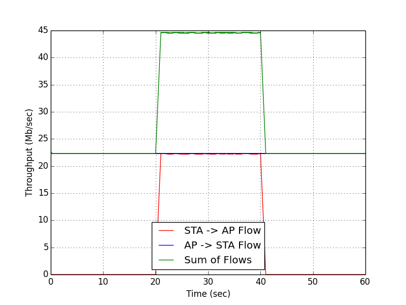
The FDD extension can be characterized using the standard experiment framework example scripts. For example, running log_capture_two_node_two_flow.py and analyzing the resulting log files with log_process_throughput_vs_time.py produces the following throughput-vs-time plot:

For this example we connected the nodes with two RF cables (RF A<->RF A and RF B<->RF B) with 50dB series attenuation on both links. Because NoMAC implements no actual medium access protocol, this FDD implementation is sensitive to interference from other devices in the 2.4GHz and 5GHz bands. Testing with cables connections eliminates this interference for the purpose of this study.
Recall from the Dual-Node Log Capture Example that the traffic pattern starts off with a constant bit rate LTG flow from AP to STA. In the middle third of the experiment, another constant bit rate LTG flow from STA to AP is enabled. Normally with the DCF, this second flow splits the sum throughput roughly evenly between the two nodes while the overall sum throughput slightly decreases due to unavoidable wireless collisions. With the FDD design, however, we can see that the presence of the second flow has no impact on the original flow and the sum throughput doubles.
(1) This app note intentionally does not use the DCF application in CPU Low. The 802.11 DCF is designed explicitly for TDD operation. The DCF assumes all nodes transmit and receive on a common channel and that nodes cannot transmit while receiving. Further it seeks to achieve transmission by 1 node at a time with well-defined rules for when nodes are allowed to transmit following activity on the common channel. All these properties are incompatible with FDD. Building a random-access MAC for an FDD system would be an interesting project but is far beyond the scope of this app note.
Attachments (1)
- Two_Node_Througput_vs_Time.png (37.0 KB) - added by chunter 7 years ago.
Download all attachments as: .zip