| Version 12 (modified by chunter, 12 years ago) (diff) |
|---|
Introduction to the Xilinx Platform Studio (XPS)
(compatible with WARP v2 and WARP v3)
In this exercise, users will be introduced to the Xilinx Platform Studio (XPS). This tool is used by designers to build complete systems out of separate peripheral cores known as "pcores." In this exercise, user's will extend a provided template project by adding a custom pcore that implements a pseudorandom number generator (PRNG) directly in the FPGA. This core is then connected to the template project's User I/O core so it can drive random values out to LEDs and hexadecimal displays.
Prerequisites
- You have a WARP v2 or WARP v3 board
- ESD protection for the WARP board (wrist strap, etc)
- WARP v2: USB cable for programming and USB cable for UART
- WARP v3: External USB JTAG cable and a micro USB cable for UART
- Complete installation of ISE System Edition 13.4
- Set up a terminal on your computer using PuTTY or an alternative. Instructions to do this are available instructions here?.
- Familiarity with the Xilinx SDK. Make sure you have completed the Introduction to the SDK exercise.
Overview

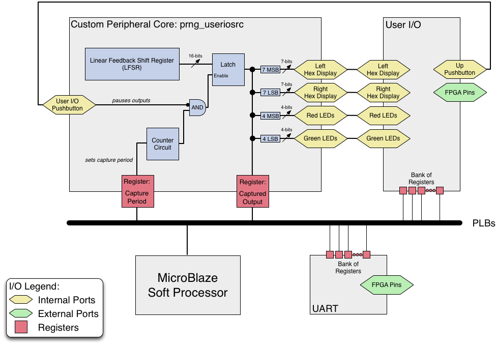
In this exercise, we provide users with a custom peripheral core: the prng_useriosrc. This core is a pseudorandom number generator with ports that are meant to be connected to the User I/O core that is present in the template WARP design. The above figure describes is a simplified diagram of the final after adding the custom pcore. Inside the custom core there is a Linear Feedback Shift Register (LFSR) that produces a sequence of pseudorandom values. These values are then latched by a counter circuit to slow them down and make their changes visible to the naked eye when observing a board. The output of this latch is sliced up and connected to output ports on the core. All pcores have two distinct ways of getting information into and out of the peripheral:
- Ports: Shown in yellow in the above figure, ports allow direct connectivity between peripherals. They can serve as inputs or outputs of the design.
- Registers: Shown in red in the above figure, registers allow peripherals to be controlled by software running in a Microblaze soft processor. Registers allow the core to hang off a bus such as the Processor Local Bus (PLB) and allow custom C-code to read or write memory addresses to control the core.
The prng_useriosrc pcore has the following inputs and outputs:
Inputs
- User I/O Pushbutton Port: This port is connected directly to the User I/O "up" pushbutton port. When the user presses the button on the board, the latch inside the prng_useriosrc core will stop updating the outputs. This will effectively "pause" the core and allow the user to read the current set of outputs from the LEDs and other display elements.
- Capture Period Register: This register attaches to the bus and allows C-code executing inside the MicroBlaze to control how often the latch on the LFSR triggers. In effect, this is a way for C-code to control how fast the output updates occur. Note: even though we have listed this as an input to the core, this register can also be read by the C-code in order to check and see what it had been set to.
Outputs
- Left/Right Hex Display Port: The left and right
Instructions
- Download either the WARP v3 Template Project or the WARP v2 Template Project? according to the which hardware you are using. Note: We recommend using the "lite" template for this exercise as it will build the quickest.
- Extract the archive into a folder on your hard drive. Note: this folder must not contain any spaces in the path (this includes the the Windows desktop, as that lives in a folder known as "Documents and Settings").
- Download the provided pcore. Unzip the archive and place the "prng_useriosrc_plbw_v1_02_a" folder inside the "pcores" folder in the extracted template project. For the purpose of this exercise, we have provided this pcore as an example of a hardware peripheral you may want to integrate into your design. The Exporting pcores from System Generator? exercise explains takes you through how this pcore was created.
WARP v3 Template Project - Lite
Board serial number: W3-a-00006
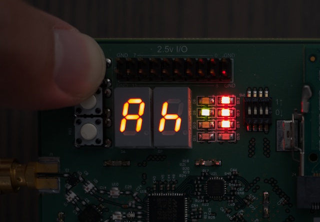
Running User I/O Example
Left Hex ------------- ------------- Right Hex
Red LEDs ------- ------- Green LEDs
PRNG Captured Value: 1 1 1 0 1 1 1 0 1 1 1 1 0 1 0 0

Attachments (9)
- output.jpg (67.5 KB) - added by chunter 12 years ago.
- prng_useriosrc_plbw_v1_02_a.zip (82.4 KB) - added by chunter 12 years ago.
- projecttab.png (177.4 KB) - added by chunter 12 years ago.
- busconnection.png (195.0 KB) - added by chunter 12 years ago.
- portconnection.png (287.6 KB) - added by chunter 12 years ago.
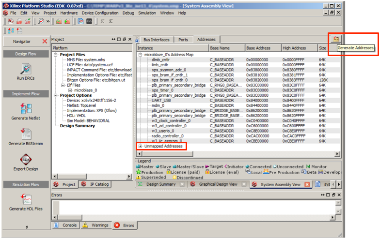
- generateaddresses.png (259.7 KB) - added by chunter 12 years ago.
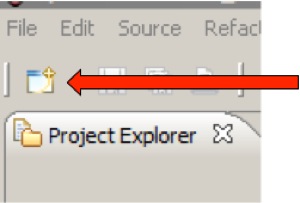
- newbutton.jpeg (14.8 KB) - added by chunter 12 years ago.
- overview.png (106.2 KB) - added by chunter 12 years ago.
- prng_example.c (6.3 KB) - added by chunter 11 years ago.
Download all attachments as: .zip