WARP User I/O Board | LEDs & Buzzer
The user I/O board provides 8 discrete LEDs and a piezo buzzer.
LEDs
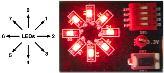
There are 8 red LEDs arranged in a circle. Each LED is tied to a dedicated FPGA pin. When the FPGA drives a logic 1, the corresponding LED illuminates. The figure below shows the orientation of the LEDs.
The pinout information for each button is listed below. The FPGA pins listed here correspond to WARP FPGA Board v1.2.
LEDs - Pinout
| LED | Header Pin | Slot 1 Pin | Slot 2 Pin | Slot 3 Pin | Slot 4 Pin |
| 0 | 47 | P10 | AC10 | AK36 | T38 |
| 1 | 48 | P8 | AB8 | AL37 | R35 |
| 2 | 49 | P1 | AB7 | AJ33 | R34 |
| 3 | 50 | P2 | AF4 | AJ35 | T36 |
| 4 | 52 | N5 | AC9 | AL35 | U38 |
| 5 | 53 | M3 | AD6 | AF32 | R29 |
| 6 | 54 | N6 | AC8 | AJ32 | U35 |
| 7 | 55 | L6 | AD7 | AE32 | T37 |
Buzzer
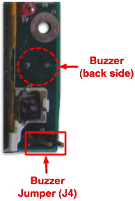
The buzzer is a Soberton GT-0930RP2 (datasheet). The buzzer has one control pin, tied to an FPGA output through a simple transistor circuit. The buzzer will only operate when the FPGA drives a logic 1 and a shunt is mounted on J4 (see image below). The pitch and volume can be controlled by modulating the frequency and duty cycle of the digital output driving the buzzer.
LEDs - Pinout
| Header Pin | Slot 1 Pin | Slot 2 Pin | Slot 3 Pin | Slot 4 Pin |
| 117 | P3 | Al2 | AD34 | P39 |

