| Version 1 (modified by murphpo, 11 years ago) (diff) |
|---|
WARPLab 7 Example: Multi-Node Synchronization
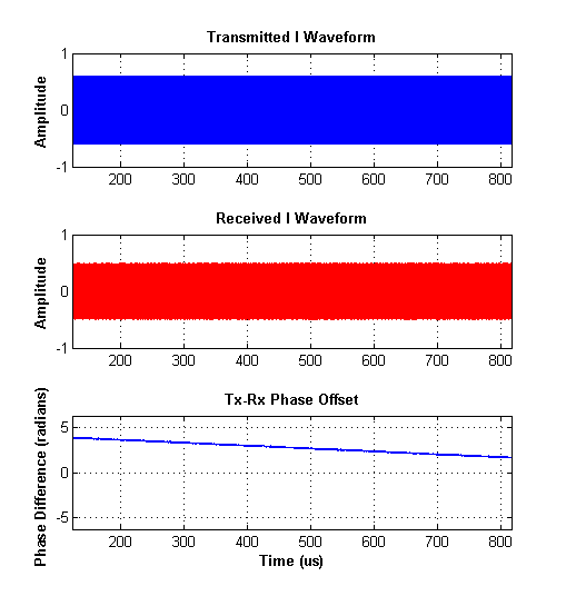
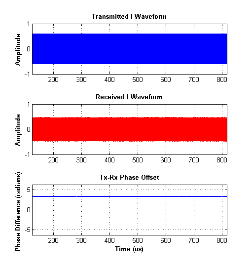
This WARPLab example illustrates how to share clocks and triggers among WARP nodes to eliminate all timing and frequency offsets. This configuration has many uses. For example, when developing a new PHY it can be helpful to test performance with zero carrier frequency offset (CFO). This same configuration can also be used to synchronize multiple nodes for large-scale MIMO experiments, where the RF interfaces of multiple nodes are used together to form a meta node with many antennas.
Setup
Requirements:
- WARPLab reference design 7.1.0 or later
- 2 WARP v3 nodes
- 2 CM-MMCX clock modules (one per WARP v3 node)
- 2 MMCX cable assemblies
- 1 twisted pair cable assembly
To run this example, you must setup your experiment as follows:
- Mount the CM-MMCX modules on each WARP v3 node. Power must be off when mounting/unmounting a clock module.
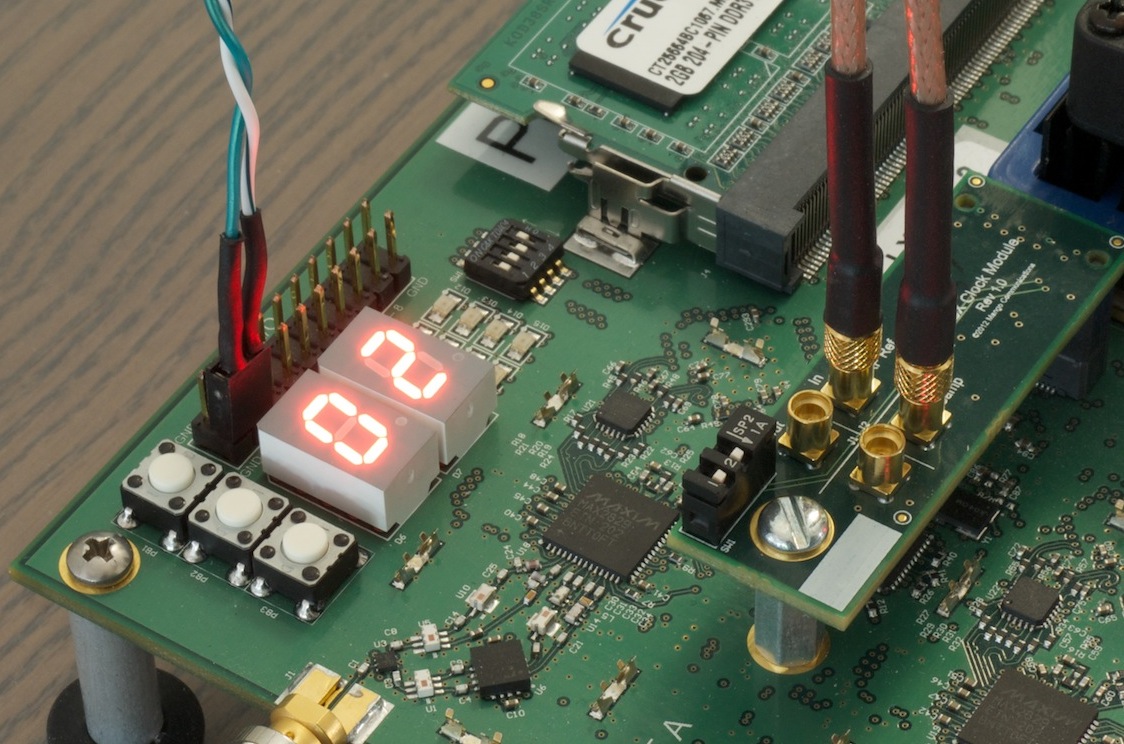
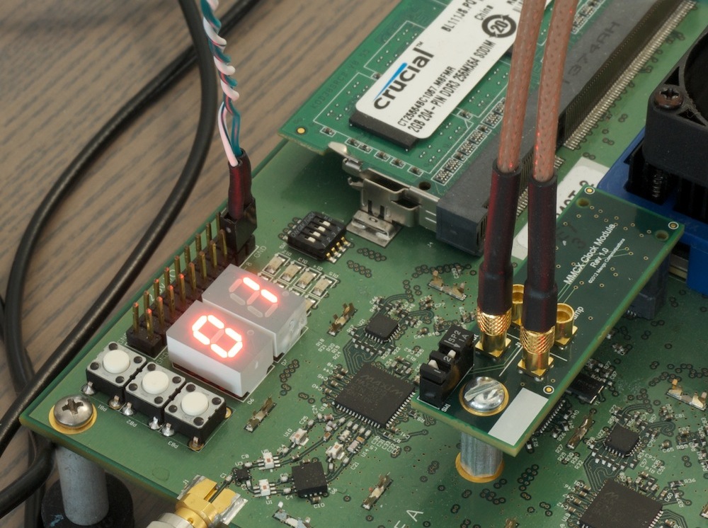
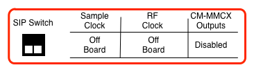
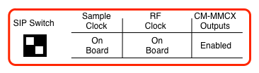
- Set the CM-MMCX switches on each node (see figure below); one node will be the clock source, the other will be the clock sink.
- Connect MMCX cables from the outputs of the source node to the inputs of the sink node.
- Connect the twisted pair cable between the debug headers of the WARP v3 boards. Pin 8 of the source node should connect to pin 15 of the sink node. Use the other conductor of the cable to connect ground between nodes (see figure below).
- Set the DIP switches on the WARP v3 boards to 0000 (source node) and 0001 (sink node).
- Power on the WARP v3 nodes
- Download the WARPLab reference bitstream to both nodes (source node first). Both nodes should boot, with the source node showing "01" on the hex displays and the sink showing "02".
Once the hardware is connected and programmed you can run the example m code: wl_example_siso_txrx_nodeSync.m.
Attachments (6)
- nodeSync_hwCfg_sink.jpg (259.3 KB) - added by murphpo 11 years ago.
- nodeSync_hwCfg_source.jpg (241.6 KB) - added by murphpo 11 years ago.
- nodeSync_CFO.png (7.2 KB) - added by murphpo 11 years ago.
- nodeSync_constPhaseOffset.png (6.9 KB) - added by murphpo 11 years ago.
- SIP_clock_sink.png (9.3 KB) - added by welsh 11 years ago.
- SIP_clock_source.png (9.4 KB) - added by welsh 11 years ago.
Download all attachments as: .zip