| Version 1 (modified by murphpo, 11 years ago) (diff) |
|---|
WARPLab 7
- Downloads
Getting Started
- Sample Buffer Sizes
- Automatic Gain Control
- Examples
- Extending WARPLab
- Debugging Errors
- Porting Code
- Benchmarks
WARPLab 7 Framework
WARPLab 7 Reference Design
Reference Design Modules
- Node
Interface Group
Baseband
Transport
Trigger Manager
Hardware
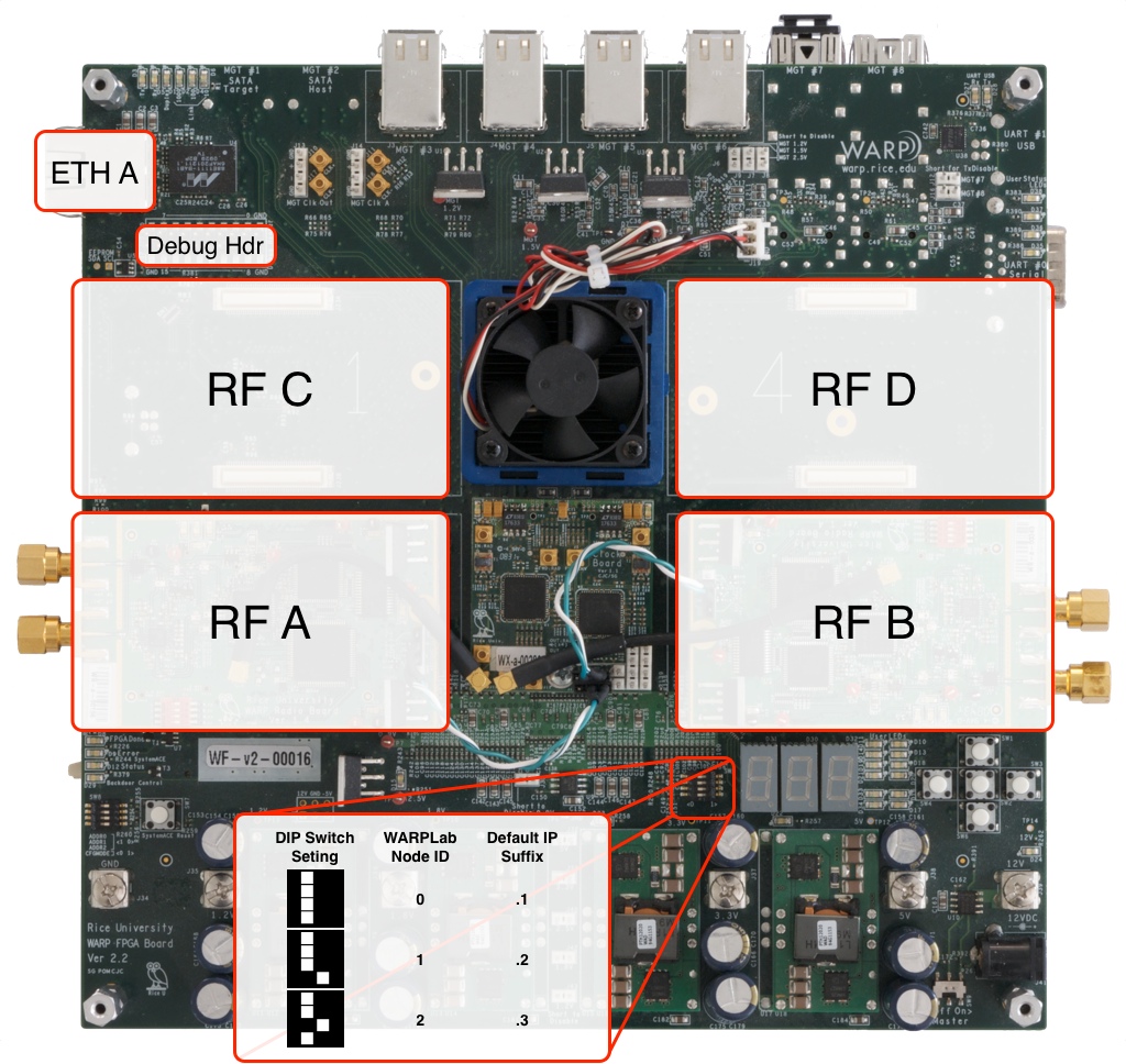
WARPLab Reference Design Hardware Config: WARP v2

Radio Interface
- In the 2 RF Node configuration (ie only RF A and RF B are populated), you should only use the 2RF bitstream in the download.
- In the 4 RF Node configuration (ie all RF interfaces are populated), you should only use the 4RF bitstream in the download.
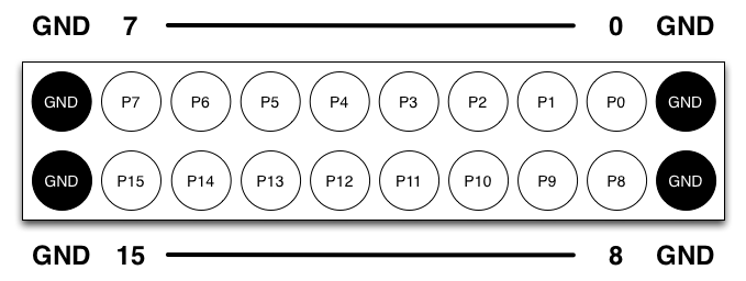
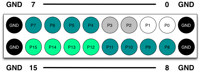
Debug Header
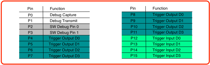
The debug header is configured by default to map to the following pins:

Clock Configuration
- Detailed information on the WARP v2 Clocking configuration can be found here.
- To adjust the HardwareUsersGuides/ClockBoard_v1.1
Ethernet
- Only one Ethernet connection (Eth A) on the board
Attachments (4)
- Debug_Header_Diagram_BnW.png (27.8 KB) - added by welsh 11 years ago.
- WARP_v2_labelled.jpg (357.1 KB) - added by murphpo 10 years ago.
- Debug_Header_Diagram.png (43.2 KB) - added by welsh 9 years ago.
- Debug_Header_Connections.png (38.1 KB) - added by welsh 9 years ago.
Download all attachments as: .zip