Assigning Addresses for Peripherals in XPS for WARPLab
Due to changes within the WARPLab Architecture to improve performance, XPS is no longer able to generate addresses for peripherals automatically. This is primarily due to the added complexity within the interconnect to improve bandwidth while still meeting the timing constraints. Therefore, it has become necessary to be able to manually assign addresses to peripherals. This tutorial will help understand addressing within WARPLab and allow you to add custom peripherals into the WARPLab Reference design.
NOTE: This tutorial is based on WARPLab 7.3.0 but the concepts should apply generically.
Understanding the FPGA Architecture
The first key to being able to manually assign addresses to peripherals is to have an understanding of the FPGA Architecture. If we look at the WARPLab 7.3.0 Architecture, we can see that there are 4 interconects: AXI 0, AXI 1, AXI Lite 0 and AXI Lite 1. Depending on where you connect your peripheral, this will determine what Masters have access to the peripheral as well as what address range to use for your peripheral.
Microblaze Configuration
To start, we need to first understand the address ranges of each interconnect. This starts with the configuration of the Microblaze processor:
The Microblaze processor supports a 32 bit address space. For WARPLab 7.3.0, we have divided the address space in half between the cache buses (ie M_AXI_DC and M_AXI_IC) and the peripheral buses (ie M_AXI_DP and M_AXI_IP). Unfortunately, the size of many address spaces, such as the caches, DDR, etc., must be aligned to powers of 2 in order to reduce address decode complexity. Therefore, if we want to use both the peripheral and cache buses, the largest address size aligned to a power of 2 that is less than 4GB is 2GB. Hence, any peripheral accessed via the M_AXI_DC bus must have an address greater than 0x8000_0000 while any peripheral accessed via the M_AXI_DP bus must have an address less than 0x8000_0000.
AXI Interconnect Configuration
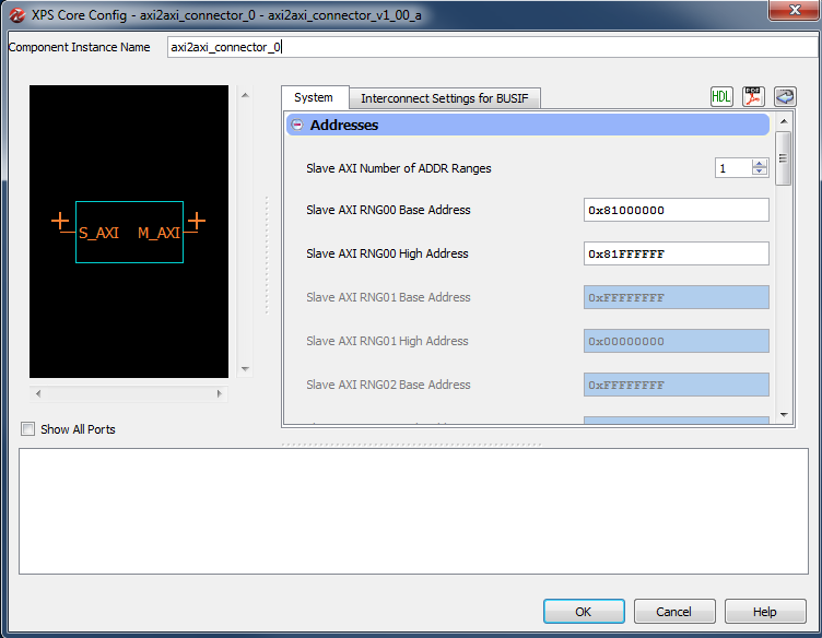
The next thing to understand are the address ranges of the AXI / AXI interconnects. To do this, it is necessary to look at the axi2axi_connector peripherals within the WARPLab design. There are two axi2axi_connector peripherals in the WARPLab 7.3.0 reference design which have the following configurations:
AXI2AXI Connector 0
AXI2AXI Connector 1
These connectors define the range of addresses that are passed to the secondary interconnect. If the address is not decoded by the connector then it is available in the original interconnect attached to the M_AXI_DC or M_AXI_DP buses. Therefore, if we look at the WARPLab 7.3.0 reference design, we have the following configuration:
| IP Instance | Base Address | High Address | Size |
|---|---|---|---|
| AXI Lite 0 | 0x0000_0000 | 0x3FFF_FFFF | 1GB |
| AXI Lite 1 | 0x4000_0000 | 0x4FFF_FFFF | 256M |
| AXI Lite 0 | 0x5000_0000 | 0x7FFF_FFFF | 768M |
| AXI 0 | 0x8000_0000 | 0x80FF_FFFF | 16M |
| AXI 1 | 0x8100_0000 | 0x81FF_FFFF | 16M |
| AXI 0 | 0x8200_0000 | 0xFFFF_FFFF | 2G - 32M |
Therefore, depending on where you connect your peripheral, you will need to use an address in one of the following ranges.
Modifying Addresses in XPS
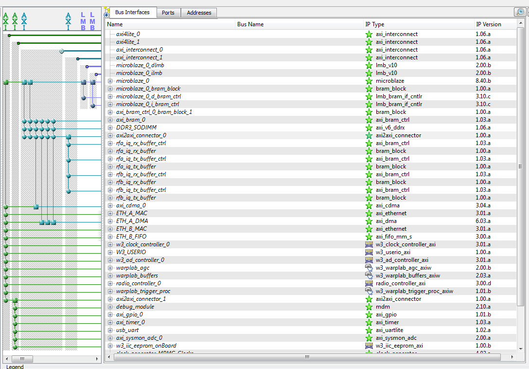
When you open the WARPLab 7.3.0 reference design in XPS, you should see the following:
This provides a high level view of the bus connections of the peripherals in the WARPLab reference design. As you can see, each of the AXI interconnect buses are shown in the columns on the left and the connection to the slave port of a peripheral is shown by a dot. For example, the W3_USERIO peripheral is connected to the axi4lite_0 bus.
When you add your peripheral to the WARPLab reference design, you need to determine which interconnect you are going to attach it to. Please note that AXI interconnects cannot have more than 16 slaves. Also, the more peripherals on an interconnect, the more logic it takes to decode and route transactions which can lead to timing problems if the design is too aggressive.
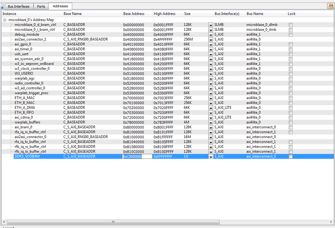
Once you have connected your peripheral to an interconnect, you then need to select the "Addresses" tab:
If you select the "Base Address" of your peripheral, then you can enter the hexadecimal base address of your peripheral on a power of 2 boundary. The "High Address" will automatically be modified based on the address size of your peripheral. You just need to make sure that you choose an appropriate address based on where your peripheral is connected.
For example, if your peripheral is connected to AXI Lite 1, then you should make sure that the number you enter for the "Base Address" is between 0x4000_0000 and 0x4FFF_FFFF.
If you have any questions, please use the forums.
Attachments (5)
- xps_addresses_highlight.png (67.5 KB) - added by welsh 10 years ago.
- axi2axi_connector_1.png (40.9 KB) - added by welsh 10 years ago.
- axi2axi_connector_0.png (47.1 KB) - added by welsh 10 years ago.
- Microblaze_Configuration.png (68.3 KB) - added by welsh 10 years ago.
- xps_bus_interfaces.png (105.3 KB) - added by welsh 10 years ago.
Download all attachments as: .zip


