| Version 11 (modified by chunter, 12 years ago) (diff) |
|---|
Exporting a Peripheral Core from System Generator
(compatible with WARP v2 and WARP v3)
In the Introduction to XPS exercise, a peripheral core is provided and users connect it to the rest of the system specified in a WARP template XPS design. In this exercise, users will learn how to create this peripheral core from a tool known as Xilinx System Generator (SysGen).
Prerequisites
- You have a WARP v2 or WARP v3 board
- ESD protection for the WARP board (wrist strap, etc)
- WARP v2: USB cable for programming and USB cable for UART
- WARP v3: External USB JTAG cable and a micro USB cable for UART
- Complete installation of ISE System Edition 13.4
- Installation of Matlab 2011a or 2011b
- Set up a terminal on your computer using PuTTY or an alternative. Instructions to do this are available instructions here?.
Overview

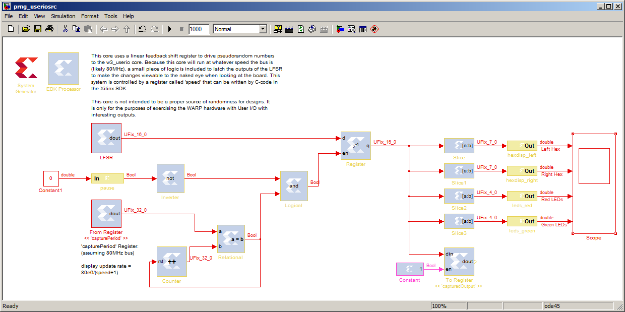
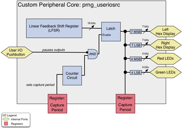
In this exercise, we provide users with a custom design that uses a Linear Feedback Shift Register (LFSR) to produce a sequence of pseudorandom values. These values are then latched by a counter circuit to slow them down and make their changes visible to the naked eye when observing a board. The output of this latch is sliced up and connected to output ports. This design is provided as a Xilinx System Generator model. In this exercise, users will export this model to create the pcore that was provided in the Introduction to XPS exercise.
Instructions
- Download the System Generator Model to a new folder on your computer and open it in Matlab

System Generator is a graphical design environment. As you can see, the actual design fairly closely resembles the block diagram shown earlier in the "Overview" section.
- Click on the small "play" button at the top of the screen (the arrow to the left of the number box that contains 1000). This will simulate the design.
- Double-click on the Scope block on the far right of the screen.

Click the small icon of the binoculars on the scope to have it choose reasonable automatic axes for the plots. This shows the output of the model: four random sequences to drive the User I/O core. Notice that the range of the top two subplots is different than the range of the bottom two due to the size of the output slices and ports (7 bits vs. 4 bits).
Additional Questions and Feedback
If you have any additional questions about this exercise or other feedback, please post to the WARP Forums.
Attachments (4)
- model.png (65.5 KB) - added by chunter 12 years ago.
- prng_useriosrc.mdl (157.5 KB) - added by chunter 12 years ago.
- scope.png (75.2 KB) - added by chunter 12 years ago.
- overview.png (56.2 KB) - added by chunter 12 years ago.
Download all attachments as: .zip