| Version 2 (modified by murphpo, 11 years ago) (diff) |
|---|
WARP v3 User Guide: Mechanical
A mechanical drawing of the WARP v3 rev1.1 PCB is available here: Mango_WARPv3_rev1p1_Mech.pdf.
Mounting Holes
The WARP v3 PCB has many mounting holes. See the figure below for the hole labels. Refer to the PDF drawing above for hole dimensions and locations.
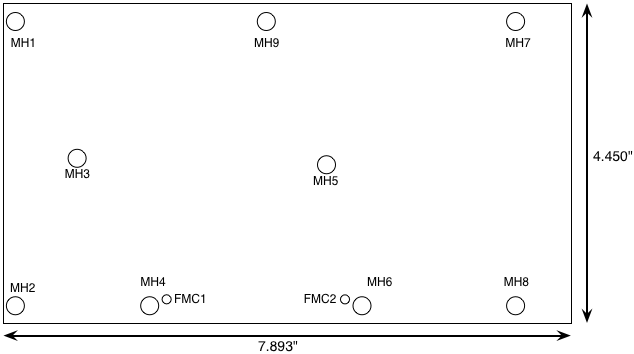
On standard WARP v3 kits:
- MH1, MH2, MH5, MH7 and MH8 are used for board standoffs (0.75" aluminium posts with rubber feet)
- MH3 is reserved for securing Clock Modules
- MH9 is covered by the SO-DIMM
The MHx holes accomodate standard 4-40 machine screws.
The holes labeled FMC1 and FMC2 are specified in the FMC standard. Compliant FMC modules (including Mango's FMC-RF-2X245 and FMC-BB-4DA) have matching holes. When an FMC module is mounted these holes are used to secure the module to the WARP v3 PCB. The nearby mounting holes (MH4, MH6) can be fitted with additional standoffs by the end user to provide additional support for FMC modules. The FMCx holes accomodate standard M2.5 machine screws.