| Version 9 (modified by chunter, 9 years ago) (diff) |
|---|
WARPLab: Automatic Gain Control
WARPLab includes the option to automatically adjust receiver gains based on the power and structure of an incoming waveform. Additionally, the AGC optionally provides built-in mechanisms for subtracting DC offset (DCO) terms in the received waveform before the waveform is presented to the host MATLAB environment. Both AGC and DCO make certain assumptions about the received waveform. This document clarifies these assumptions so that users can make an informed decision on whether the use of the AGC and/or DCO correction subsystems is appropriate given their specific use case.
Gain Selection based on RSSI and Received I/Q
The MAX2829 transceiver in WARP's radios has two stages of Rx gain: a low noise amplifier (LNA) that can provide up to 30 dB of amplification followed by a baseband gain that can provide up to 63 dB of additional amplification. Together, these gain stages can provide up to 93 dB of gain to a received signal. The AGC core provided with WARPLAB selects these two gains in three sequential stages:
- When triggered, the AGC first selects an LNA gain based upon the RSSI signal provided by the transceiver. It does this by first converting the digital RSSI measurement into an receive power estimate in dBm. With this value, the AGC chooses one of the three possible LNA gain settings that minimizes EVM. The MAX2829 datasheet provides graphs that show EVM for each LNA gain setting as a function of receive power.
- The act of changing the LNA gain affects the RSSI measurement. After RSSI has a chance to settle from the previous LNA gain adjustment, the value is re-read and is used to make an initial, coarse, update to the baseband gain stage.
- After the both the LNA gain and the baseband gain have been adjusted based on RSSI, a final refinement to the baseband gain is made by the AGC based upon waveform's I and Q values themselves. Prior to this stage, the waveform cannot be trusted for an accurate power measurement since it is likely saturating the radio's ADCs. Using the waveform's I and Q values to refine the baseband gain introduces an important waveform dependence -- during the window that the AGC inspects the I/Q waveform, the magnitude of the signal must be periodic in 16 40-MHz samples. A series of 20 MHz-wide 802.11 STS symbols meets these requirements.
DC Offset Correction based on Received I/Q
After the final gain adjustments are made, the AGC core can optionally subtract any detected DC offset. This also produces an waveform dependence -- the transmitted I and Q waveforms must be zero mean over a period of 32 samples. A series of 20 MHz-wide 802.11 STS symbols meets these requirements.
Waveform Dependence
The periodicity requirements of the AGC and DCO correction systems can be achieved by many different waveforms. One common waveform that meets the requirements is the 802.11 short training symbol. This 20 MHz-wide waveform is used by 802.11 for the purposes of AGC and DCO correction. It can be used as a WARPLab preamble even if the proceeding waveform has no relation to 802.11.
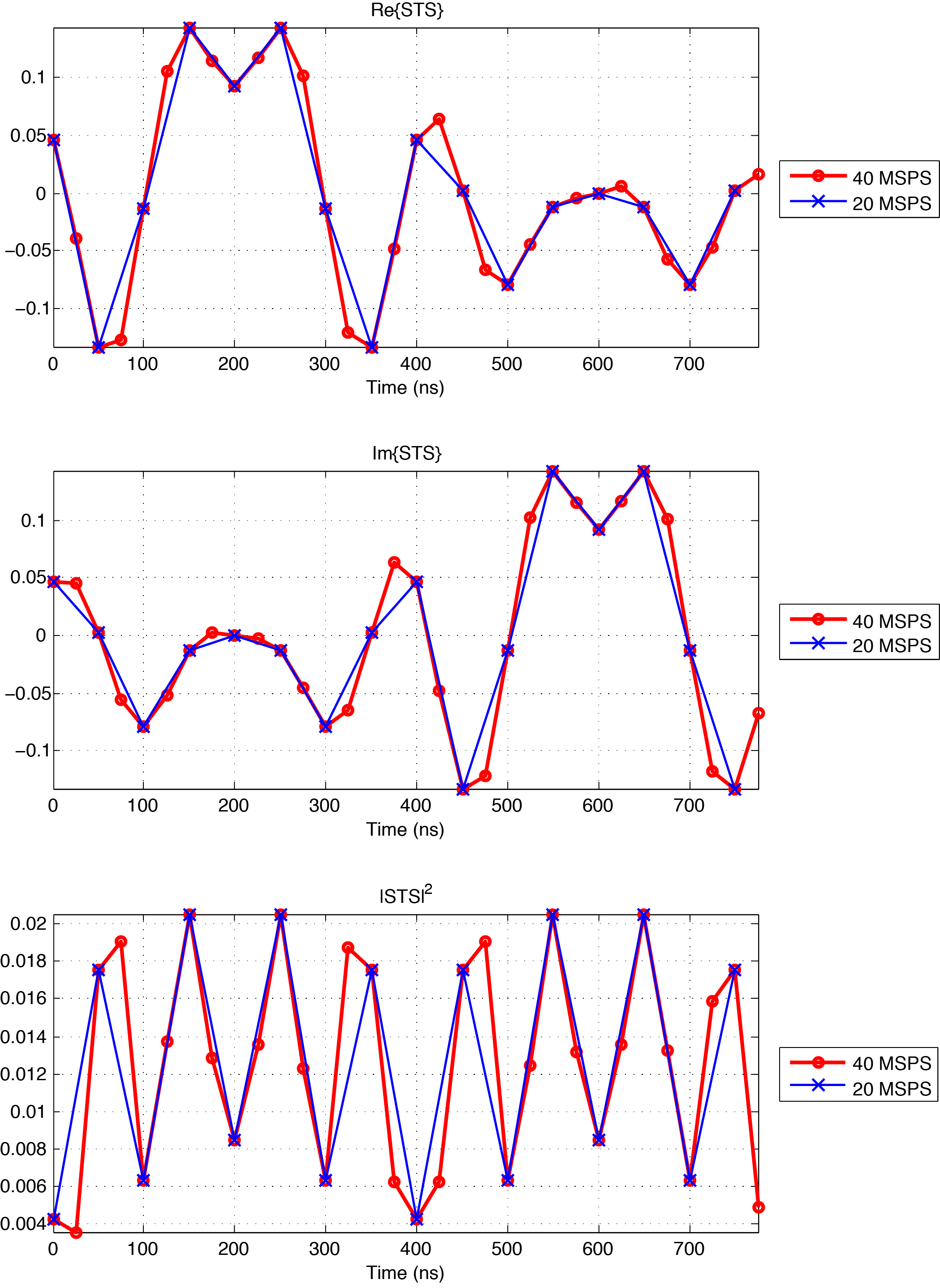
 20 MHz STS Symbol |
The above figure shows a single 20 MHz STS symbol for both a 20 MSPS system (as defined by the 802.11 standard) and a 40 MSPS system (e.g. WARPLab). When 2x oversampled in a 40 MSPS system, the STS itself is periodic in 32 samples, achieving the requirements for the DCO correction subsystem. The magnitude-squared (I2 + Q2), however, is periodic in 16 samples. This achieves the requirements for the baseband gain refinement in the AGC.
Even though the AGC is tuned for a 20 MHz STS, it is important to note that this does not limit the overall WARPLab design from dealing with wider-bandwidth waveforms. Even the 40 MHz 802.11n standard still uses 20 MHz STS symbols by forming two valid 20 MHz preambles that on neighboring 20 MHz channels. Doing so still meets the periodicity requirements of the AGC and DCO correction subsystems.
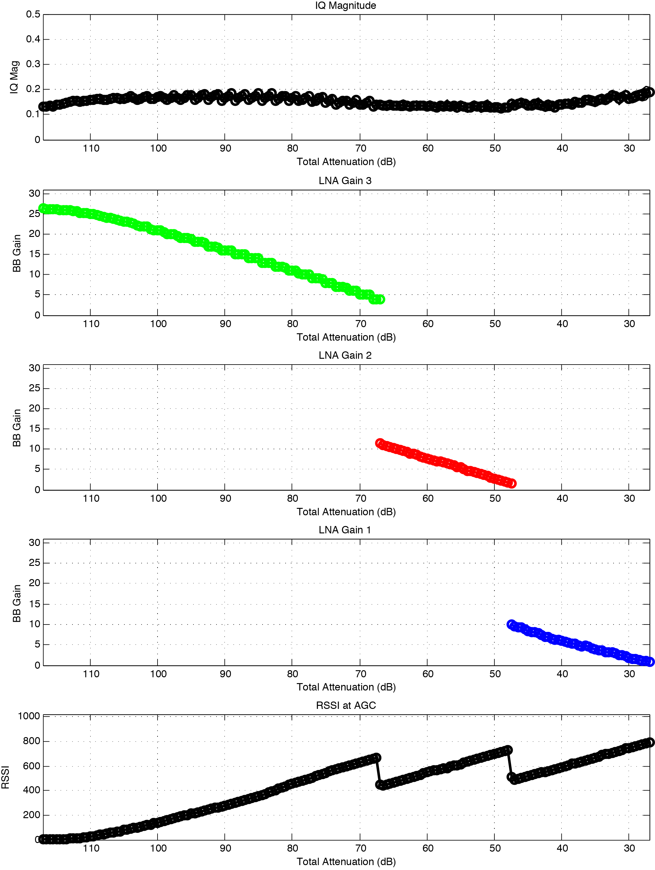
AGC Characterization
To characterize the AGC, we use the Aeroflex 4205 programmable attenuator in conjunction with 20 dB of fixed attenuation to sweep a 90 dB of receive powers. At each receive power, we let the AGC choose gains and plot the resulting I/Q magnitude in WARPLab.
 AGC Characterization |
The above image shows that the AGC performs adequately over the entire 90 dB range, roughly keeping the resulting I/Q magnitude flat at the ADCs.
Altering the AGC Behavior
The Baseband Buffers module contains many commands for modifying behavior in the AGC. The three most useful commands for users are:
- agc_target - This command adjusts the target gain of the AGC. A lower (i.e. "more negative") value will produce a smaller signal at the ADCs and vice versa.
- agc_dco - This command can enable or disable the DC offset correction. Depending on the waveform being used, it may make more sense to implement DC offset correction in MATLAB after a reception has occurred.
- agc_reset_per_rx - This command will configure the AGC to either reset on each trigger of the the receive state machine or to trigger once and leave the selected gains indefinitely until configured to do otherwise. This can be useful in experiments where correct gains are a priori unknown but changing gains over the course of the experiment could lead to anomalous results.
Attachments (2)
- agc_calib.png (173.9 KB) - added by chunter 9 years ago.
- sts.png (282.4 KB) - added by chunter 9 years ago.
Download all attachments as: .zip