| Version 3 (modified by chunter, 11 years ago) (diff) |
|---|
WARPLab 7
- Downloads
Getting Started
- Sample Buffer Sizes
- Automatic Gain Control
- Examples
- Extending WARPLab
- Debugging Errors
- Porting Code
- Benchmarks
WARPLab 7 Framework...
WARPLab 7 Reference Design
Reference Design Modules
- Node
Interface Group
Baseband
Transport
Trigger Manager
Hardware
Processor Trigger Manager Module
The WARPLab Reference Design implements a Trigger Manager module that handles various types of triggers that can be used to synchronize actions among multiple nodes.
Related Components:
- MATLAB:
- wl_trigger_manager_proc class
- WARP Hardware:
- warplab_trigger_proc peripheral
- wl_transport C software
User Guide
System Requirements
- Review the WARPLab 7 System Requirements
Overview
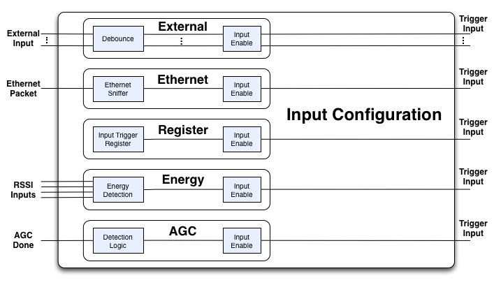
The Trigger Manager was designed to allow flexible coordination and communication between nodes. Each trigger is assigned an ID and then all configuration of the trigger manager is based on these IDs. By default, WARPLab has the following triggers:
- Input Triggers
- External Pins (For example: D0 - D3, pins 12 - 15 on the debug header in the WARPLab reference design)
- Ethernet Packets
- Register writes (used for WARP v2 compatibility)
- Input Energy
- Automatic Gain Control (AGC) Done

NOTE: Each input has configuration options that can be found in the Trigger Manager Command Reference.
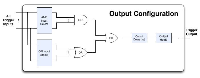
- Output Triggers
- External Pins (For example: D0 - D3, pins 8 - 11 on the debug header in the WARPLab reference design)
- Baseband
- Automatic Gain Control (AGC) Start

NOTE: Each output can be based on a configurable set of inputs as well as a logical combination of inputs. The above diagram is replicated per trigger output, so that each one can have its own, independent configuration.
Hardware Setup
The Trigger Manager consists of both a hardware block that runs within the FPGA and a software framework to configure and use the Trigger Manager. You can see the instantiation of the Trigger Manager block as well as the default connections within the system.mhs file:
# Default configuration of the Trigger Manager in system.mhs

BEGIN w3_warplab_trigger_proc_axiw
 PARAMETER INSTANCE   = warplab_trigger_proc
 PARAMETER HW_VER     = 1.01.a
 PARAMETER C_BASEADDR = 0x77800000
 PARAMETER C_HIGHADDR = 0x7780ffff
 BUS_INTERFACE S_AXI  = axi4lite_1
 BUS_INTERFACE AXI_STR_ETH_RXD = ETH_A_AXI_STR_RXD
 PORT axi_aclk        = clk_160MHz
 PORT sysgen_clk      = clk_160MHz
 # Triggers
 PORT agc_done_in = agc_is_done
 PORT debug_0_in  = trig_0_in
 PORT debug_1_in  = trig_1_in
 PORT debug_2_in  = trig_2_in
 PORT debug_3_in  = trig_3_in
 PORT rfa_rssi    = warplab_rfa_rssi
 PORT rfb_rssi    = warplab_rfb_rssi
 PORT rfc_rssi    = net_gnd
 PORT rfd_rssi    = net_gnd
 PORT rssi_clk    = warplab_rssi_clk
 PORT trig_0_out  = baseband_trigger
 PORT trig_1_out  = agc_start
 PORT trig_2_out  = trig_2_out
 PORT trig_3_out  = trig_3_out
 PORT trig_4_out  = trig_4_out
 PORT trig_5_out  = trig_5_out
END
The trig_*_in and trig_*_out signals are connected to the debug header and can be used to externally trigger events.
Examples
In our examples, we have two nodes, a transmitter ( nodes(1) ) and a receiver ( nodes(2) ):
- Create a UDP broadcast trigger and trigger the transmitting node with the Ethernet packet
eth_trig = wl_trigger_eth_udp_broadcast;
nodes(1).wl_triggerManagerCmd('add_ethernet_trigger',[eth_trig]);
NOTE: This will allow a host, like Matlab, to create an Ethernet packet to begin transmission
- Read Trigger IDs into workspace
[T_IN_ETH,T_IN_ENERGY,T_IN_AGCDONE,T_IN_REG,T_IN_D0,T_IN_D1,T_IN_D2,T_IN_D3] =  wl_getTriggerInputIDs(nodes(1));
[T_OUT_BASEBAND, T_OUT_AGC, T_OUT_D0, T_OUT_D1, T_OUT_D2, T_OUT_D3] = wl_getTriggerOutputIDs(nodes(1));
NOTE: These trigger IDs will be the same for all nodes in the system and should not be modified by the user.
- For the transmit node, allow Ethernet to trigger the buffer baseband, the AGC, and Trigger output 0 (which is mapped by default in the WARPLab reference design to pin 8 on the debug header)
nodes(1).wl_triggerManagerCmd('output_config_input_selection',[T_OUT_BASEBAND,T_OUT_AGC,T_OUT_D0],[T_IN_ETH,T_IN_REG]);NOTE: We use both T_IN_ETH and T_IN_REG so this example is compatible with both WARP v2 and WARP v3 hardware. If using WARP v3 hardware, only T_IN_ETH is needed as the source of the trigger.
- For the receive node, allow the energy detector to trigger the buffer baseband and AGC core:
nodes(2).wl_triggerManagerCmd('output_config_input_selection',[T_OUT_BASEBAND,T_OUT_AGC],[T_IN_ENERGY]);Then enable the hold mode for the triggers driven by energy detection. This will prevent the buffer from being overwritten before we have a chance to read it:nodes(2).wl_triggerManagerCmd('output_config_hold_mode',[T_OUT_BASEBAND,T_OUT_AGC],'enable');Then get the IDs for the interfaces on the board and setup the configuration of the energy monitoring:[RFA,RFB] = wl_getInterfaceIDs(nodes(2)); rssi_sum_len = 15; nodes(2).wl_triggerManagerCmd('energy_config_average_length',rssi_sum_len); nodes(2).wl_triggerManagerCmd('energy_config_busy_threshold',rssi_sum_len*500); nodes(2).wl_triggerManagerCmd('energy_config_busy_minlength',10); nodes(2).wl_triggerManagerCmd('energy_config_interface_selection',RFA+RFB);Finally, when done processing, we can clear the energy detection trigger since it is holding the output due to setting the 'output_config_hold_mode'nodes(2).wl_triggerManagerCmd('output_state_clear',[T_OUT_BASEBAND,T_OUT_AGC]);
- For the receive node, allow trigger input to trigger the buffer baseband and the AGC (this example assumes the WARPLab reference design configuration where we should connect trigger output 0, pin 8 of the debug header, of the transmit node to trigger input 3, pin 15 of the debug header, of the receive node):
nodes(2).wl_triggerManagerCmd('output_config_input_selection',[T_OUT_BASEBAND,T_OUT_AGC],[T_IN_D3]);We will also enable the debounce circuitry on the trigger input to help with noise on the signal line:nodes(2).wl_triggerManagerCmd('input_config_debounce_mode',[T_IN_D3],'enable');Since the debounce circuitry is enabled, there will be a delay at the receiver node for its input trigger. To better align the transmitter and receiver, we can artifically delay the transmitters trigger outputs that drive the buffer baseband and the AGC:nodes(1).wl_triggerManagerCmd('output_config_delay',[T_OUT_BASEBAND,T_OUT_AGC],[50]); %50ns delayNOTE: The 50 ns delay was measured using the oscilloscope. The procedure can be found here (Coming soon ...).
Getting Help
If you have any additional questions, please post to the WARP Forums.
Trigger Manager Commands
Trigger Manager commands are selected as string inputs to the wl_triggerManagerCmd method in wl_node.m. These strings are each individual cases of the switch statement in procCmd method of wl_trigger_manager.m.
Syntax
MATLAB allows two valid forms of syntax for calling methods
- Let N be a scalar or vector of wl_node objects
- Let command_string be a string containing a particular command
- Let arg be an argument for that command (optional)
Syntax 1: wl_triggerManagerCmd(N, command_string, arg1, arg2, ..., argN)
Syntax 2: N.wl_triggerManagerCmd(command_string, arg1, arg2, ..., argN)
These two different forms of syntax are identical and either may be used for issuing commands to WARP nodes.
Command List and Documentation
add_ethernet_trigger
Associates node to a trigger input
Arguments: (wl_trigger_manager TRIGGER)
Returns: none
delete_ethernet_trigger
Deassociates node to a trigger input
Arguments: (wl_trigger_manager TRIGGER)
Returns: none
clear_ethernet_triggers
Clears all trigger associations in the node
Arguments: none
Returns: none
get_ethernet_trigger
Reads current trigger association from node
Arguments: node
Returns: (uint32 TRIGGER_ASSOCIATION)
TRIGGER_ASSOCIATION: bit-wise AND of associated
trigger IDs
output_config_input_selection
Selects which trigger inputs drive the selected outputs
Arguments: (uint32 OUTPUTS), (uint32 OR_INPUTS), ![optional] (uint32 AND_INPUTS)
Returns: none
OUTPUTS: vector of output trigger IDs, provided by
wl_getTriggerOutputIDs
OR_INPUTS: vector of input trigger IDs, provided by
wl_getTriggerInputIDs. Any triggers in
this vector that assert will cause the
output trigger to assert.
AND_INPUTS: vector of input trigger IDs, provided by
wl_getTriggerInputIDs. Only if all triggers
in this vector assert will the output
trigger assert.
Usage note: This command replaces the current input
selection on the board. Previous state is not saved.
output_config_delay
Configures specified output triggers to be have an
additional delay relative to their inputs
Arguments: (uint32 OUTPUTS), (double DELAY_NS)
Returns: none
OUTPUTS: vector of output trigger IDs, provided by
wl_getTriggerOutputIDs
DELAY_NS: scalar value of the intended delay,
specified in nanoseconds (1e-9 seconds)
output_config_hold_mode
Configures whether specified output triggers should
hold their outputs once triggered
Arguments: (uint32 OUTPUTS), (string MODE)
Returns: none
OUTPUTS: vector of output trigger IDs, provided by
wl_getTriggerOutputIDs
MODE: 'enable' or 'disable'
output_state_read
Reads current state of output triggers. Note: this
command is intended to be used on output triggers
that have enabled their hold mode.
Arguments: (uint32 OUTPUTS)
Returns: (bool STATES)
OUTPUTS: vector of output trigger IDs, provided by
wl_getTriggerOutputIDs
STATES: vector of (true, false) trigger states
corresponding to state of OUTPUTS vector
output_state_clear
Clears current state of output triggers.
Arguments: (uint32 OUTPUTS)
Returns: none
OUTPUTS: vector of output trigger IDs, provided by
wl_getTriggerOutputIDs
input_config_enable_selection
Configures specified input triggers to be enabled
as inputs that feed the trigger manager core.
Note: This command disables all inputs before
enabling the selected inputs -- no previous state is
stored in the node.
Arguments: (uint32 INPUTS)
Returns: none
INPUTS: vector of output trigger IDs, provided by
wl_getTriggerInputIDs
input_config_debounce_mode
Configures specified input triggers to enable or
disable debounce circuit. Note: debounce circuit adds
delay of 4 cycles, where each cycle is a duration
specified in the delayStep_ns property of the
wl_manager_proc.m class.
Arguments: (uint32 INPUTS), (string MODE)
Returns: none
INPUTS: vector of output trigger IDs, provided by
wl_getTriggerInputIDs
MODE: 'enable' or 'disable'
energy_config_busy_threshold
Configures the threshold above which RSSI is
considered as a "busy" medium.
Arguments: (uint32 THRESH)
Returns: none
THRESH: busy threshold. For the MAX2829-based
interfaces, WARP uses a 10-bit ADC for
RSSI (range of [0,1023]).
Note: RSSI averaging in the core does NOT divide by
the number of samples that are summed together.
Averaging by N cycles means that the maximum possible
RSSI post-averaging is N*1023.
energy_config_average_length
Configures the number of samples over which RSSI is
averaged before it is compared to any threshold.
Arguments: (uint32 LENGTH)
Returns: none
LENGTH: Number of samples over which RSSI is
averaged.
Note: For all hardware versions, RSSI is sampled at
10 MHz. Each sample is, therefore, 100 ns.
energy_config_busy_minlength
Average RSSI samples must exceed the busy threshold
for a minimum number of samples before the trigger is
activated. This command sets this minimum value.
Arguments: (uint32 LENGTH)
Returns: none
LENGTH: Minimum number of samples that RSSI must
be busy before trigger is raised.
energy_config_interface_selection
Selects the interfaces from which energy detection
should base its decision
Arguments: (uint32 IFCSELECTION)
Returns: none
IFCSELECTION: One or more interfaces that the
energy detector system should
monitor
Note: IFCSELECTION is intended to be used with the
return values from the wl_getInterfaceIDs method.
test_trigger
Sends a test trigger
Arguments: none
Returns: none
Attachments (2)
- Trigger_Input_Configuration.png (48.1 KB) - added by chunter 11 years ago.
- Trigger_Output_Configuration.png (26.3 KB) - added by chunter 11 years ago.
Download all attachments as: .zip