WARP Project Forums - Wireless Open-Access Research Platform
You are not logged in.
#1 2015-Dec-01 08:55:33
- David Garcia-Roger
- Member
- Registered: 2015-Nov-03
- Posts: 10
SIP Switch [CM-MMCX Clock Module]
Hello all:
Just a quick question. Page WARPLab Reference Design Hardware Config: WARP v3 states that:
clock reference on board, reference output enabled, daisy chain position first is down, up: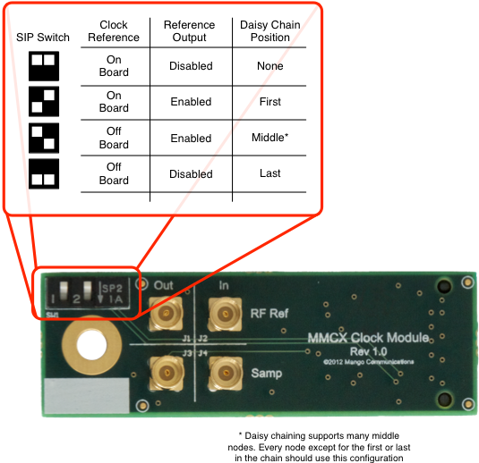
Also mentioned in WARPLab 7 Example: 8x2 Array: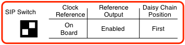
My problem is that down, up does not work for me (blinking LED Christmas tree lights on primary board).
Instead, only up, down, as in clock reference on board, reference output enabled, daisy chain position middle works.
Puzzling enough, the picture in WARPLab 7 Example: 8x2 Array shows up down (my working option).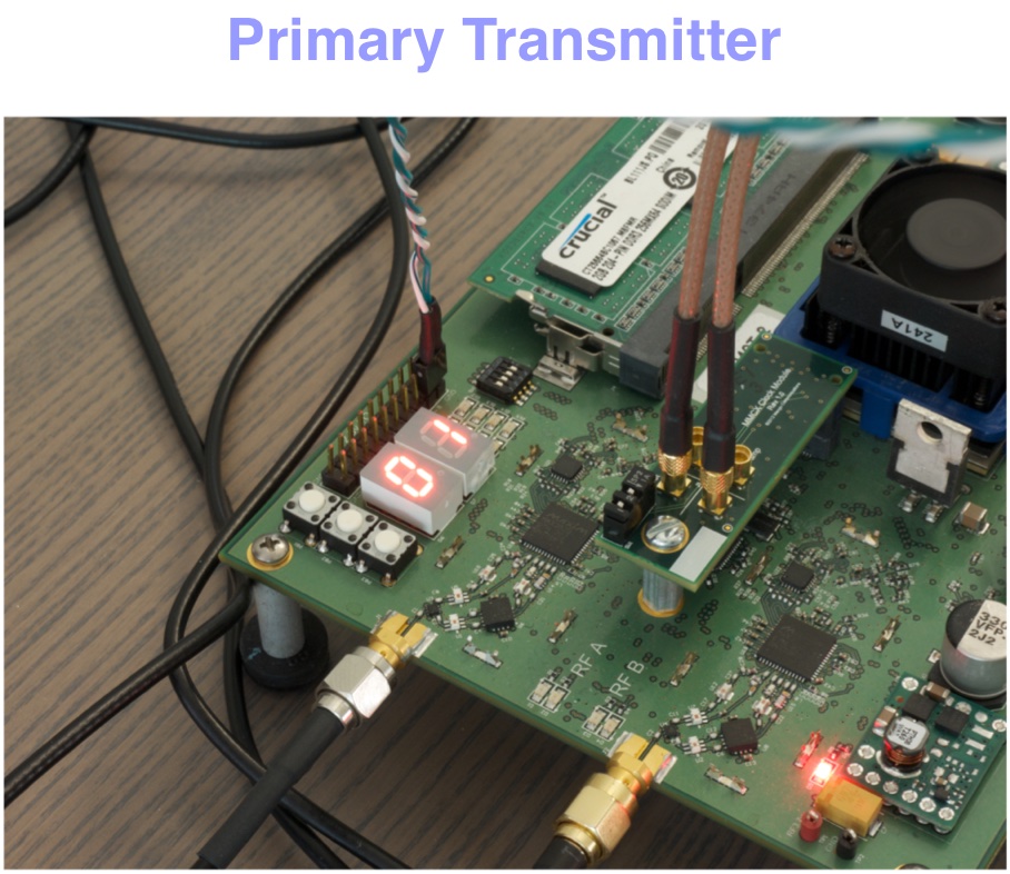
Should I understand that there is a typo in the diagrams? :)
Thanks in advance!
Offline
#2 2015-Dec-01 09:12:29
- welsh
- Administrator
- From: Mango Communications
- Registered: 2013-May-15
- Posts: 612
Re: SIP Switch [CM-MMCX Clock Module]
Which version of WARPLab are you using?
If you look at the UART output from the board, it should tell you the clock configuration during boot.
Offline
#3 2015-Dec-01 09:16:36
- David Garcia-Roger
- Member
- Registered: 2015-Nov-03
- Posts: 10
Re: SIP Switch [CM-MMCX Clock Module]
welsh wrote:
Which version of WARPLab are you using?
Hmm... version 7.4.0.
welsh wrote:
If you look at the UART output from the board, it should tell you the clock configuration during boot.
Okay, I will look there. Thank you!
Offline
#4 2015-Dec-01 10:21:27
- welsh
- Administrator
- From: Mango Communications
- Registered: 2013-May-15
- Posts: 612
Re: SIP Switch [CM-MMCX Clock Module]
Between WARPLab 7.4.0 and WARPLab 7.5.0, we added support for the CM-PLL module in the clcok controller. You can see the difference between the clock module configuration code for WARPLab 7.4.0 vs the clock module configuration code for WARPLab 7.5.0. As part of the update, the CM-MMCX SIP switch definitions changed to be more consistent with the CM-PLL module. The documentation you see is consistent with the SIP switch definitions of WARPLab 7.5.0 and later. However as you noted, the picture from the example was taken with an older version of WARPLab which used the previous definitions. You can upgrade to the latest version of WARPLab or look at the WARPLab 7.4.0 code to understand the SIP switch settings. Also, feel free to update the c code if you want the SIP switches to mean something else.
Offline
#5 2015-Dec-01 10:28:22
- David Garcia-Roger
- Member
- Registered: 2015-Nov-03
- Posts: 10
Re: SIP Switch [CM-MMCX Clock Module]
welsh wrote:
Between WARPLab 7.4.0 and WARPLab 7.5.0 [...] as part of the update, the CM-MMCX SIP switch definitions changed to be more consistent with the CM-PLL module. The documentation you see is consistent with the SIP switch definitions of WARPLab 7.5.0 and later. However as you noted, the picture from the example was taken with an older version of WARPLab which used the previous definitions. You can upgrade to the latest version of WARPLab or look at the WARPLab 7.4.0 code to understand the SIP switch settings. Also, feel free to update the c code if you want the SIP switches to mean something else.
Okay, now I understand. Thank you for your help!
Offline