Multi-hop OFDM Networking Reference Design
By default, this project creates a custom wireless ethernet hub between computers attached to two WARP boards and uses a third WARP node has a relay. The project treats ethernet packets as payload only; the WARP board performs no IP processing whatsoever. The following is an example configuration.

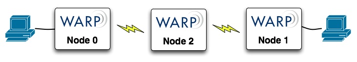
Example System Configuration 1
The user will need to supply two computers and three WARP nodes (1 node = 1 FPGA[v1.2] + 1 Radio[v1.4]). The computers need to be configured to have hardcoded IP addresses within each other's addressable range. In other words, they must be in each other's subnet to be able to talk to one another. For example, one computer can be 10.0.0.8 and the other can be 10.0.0.9 and each can have a subnet mask of 255.255.255.0.
One FPGA board must by configured as Node 0, and other as Node 1, using the on-board dip switches. The switch closest to the power supplies represents the node value. When the program is downloaded, the seven-segment LCDs should show the node values. These nodes must be connected to the computer terminals via Ethernet, as shown above. A third, Node 2, must be configured with the bitstream and stand alone. Being the relay, it needs no computer to connect to.
Note, if the PCs are using older network cards that do not support auto MDI/MDI-X, the user may need to provide crossover ethernet cables instead of standard cables. Once the boards are connected and configures, any traffic directed to one computer's IP address from the other computer will be forwarded.
Download the full reference design here: Multi-hop OFDM Reference Design (60MB .zip file).
Attachments (1)
- multihop.jpg (30.4 KB) - added by chunter 17 years ago.
Download all attachments as: .zip