WARPLab 7
- Downloads
Getting Started
- Sample Buffer Sizes
- Automatic Gain Control
- Examples
- Extending WARPLab
- Debugging Errors
- Porting Code
- Benchmarks
WARPLab 7 Framework
WARPLab 7 Reference Design
Reference Design Modules
- Node
Interface Group
Baseband
Transport
Trigger Manager
Hardware
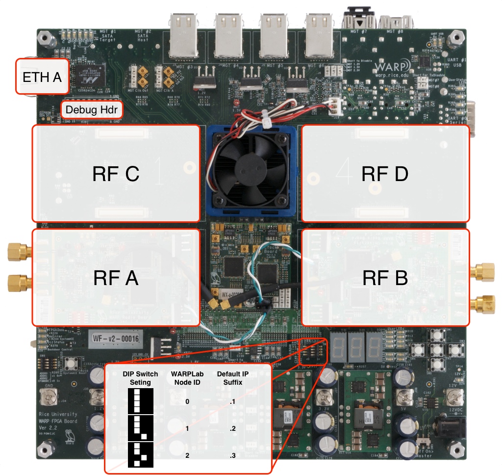
WARPLab Reference Design Hardware Config: WARP v2

Radio Interface
- In the 2 RF Node configuration (ie only RF A and RF B are populated), you should only use the 2RF bitstream in the download.
- In the 4 RF Node configuration (ie all RF interfaces are populated), you should only use the 4RF bitstream in the download.
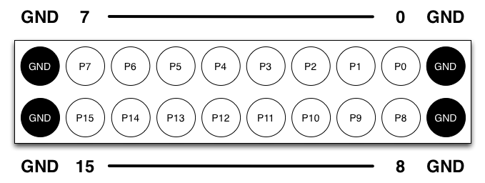
Debug Header
Updated for WARPLab 7.5.1
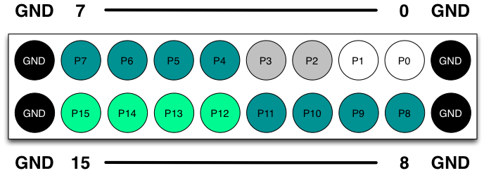
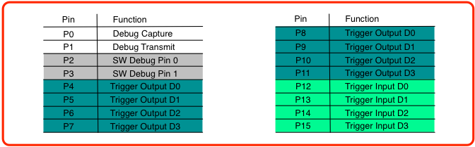
The debug header is configured by default to map to the following pins:


NOTE: The Debug Header is defined in the system.ucf and the connections are defined in the system.mhs
- The Trigger output and Trigger input pins above are used with the Trigger Manager
Clock Configuration
The WARPLab reference design does not require any external clock connections. By default the reference design will use the oscillators on the WARP v2 board for all system and RF clocking.
The reference design does support both sourcing and sinking external clocks for synchronization of multiple nodes. The WARP v2 kit must be equipped with a clock board to source/sink clocks.
- Detailed information on the WARP v2 Clocking configuration can be found here.
- Detailed information on the WARP v2 Clock Board can be found here.
The WARPLab Reference Design assumes the Clock and Radio Boards are connected according to the specs in the Clock Connection howto.
Ethernet
- Only one Ethernet connection (Eth A) on the board
- Please note that due to hardware limitations within Xilinx peripherals, WARP v2 only supports non-jumbo Ethernet frames up to 1514 bytes.
Attachments (4)
- Debug_Header_Diagram_BnW.png (27.8 KB) - added by welsh 11 years ago.
- WARP_v2_labelled.jpg (357.1 KB) - added by murphpo 11 years ago.
- Debug_Header_Diagram.png (43.2 KB) - added by welsh 9 years ago.
- Debug_Header_Connections.png (38.1 KB) - added by welsh 9 years ago.
Download all attachments as: .zip