| Version 2 (modified by welsh, 11 years ago) (diff) |
|---|
WARPLab 7
- Downloads
Getting Started
- Sample Buffer Sizes
- Automatic Gain Control
- Examples
- Extending WARPLab
- Debugging Errors
- Porting Code
- Benchmarks
WARPLab 7 Framework
WARPLab 7 Reference Design
Reference Design Modules
- Node
Interface Group
Baseband
Transport
Trigger Manager
Hardware
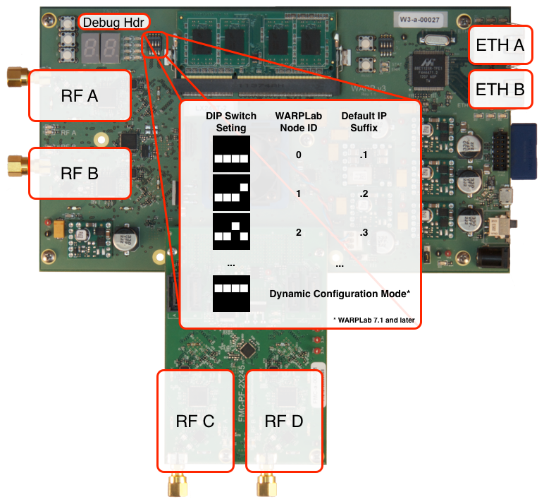
WARPLab Reference Design Hardware Config: WARP v3

Radio Interface
- In the 2 RF Node configuration (ie only RF A and RF B are populated), you should only use the 2RF bitstream in the download.
- In the 4 RF Node configuration (ie all RF interfaces are populated), you should only use the 4RF bitstream in the download.
Dip Switches
- In WARPLab 7.1 and later, the dip switch value of 0xF (ie all switches set to '1'), is reserved for dynamic node configuration.
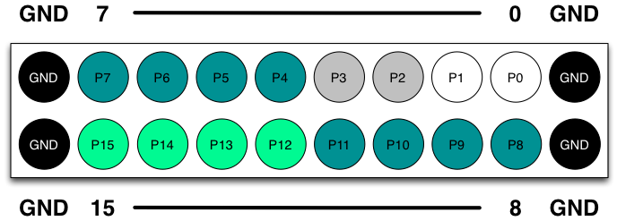
Debug Header
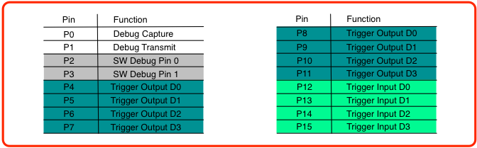
The debug header is configured by default to map to the following pins:

 | These pins are not 3.3v compatible! You must use external level shifting to interface with non-2.5v signals. |

NOTE: The Debug Header is defined in the system.ucf and the connections are defined in the system.mhs
- The Trigger output and Trigger input pins above are used with the Trigger Manager
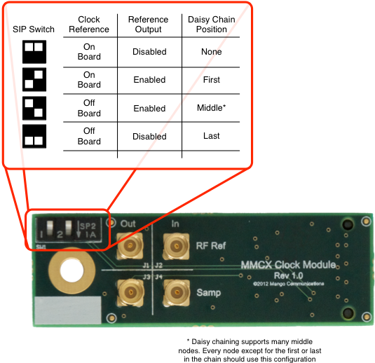
Clock Configuration
The WARPLab reference design does not require any external clock connections. By default the reference design will use the oscillators on the WARP v3 board for all system and RF clocking.
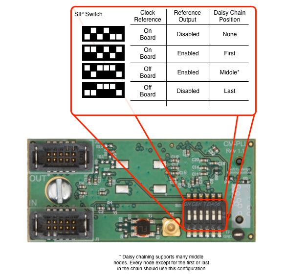
The reference design does support both sourcing and sinking external clocks for synchronization of multiple nodes. The WARP v3 kit must be equipped with a CM-MMCX Clock Module to source/sink clocks. The role of each node is configured via the 2-position SIP switch on the CM-MMCX, according to the figure below.
- Detailed information on the WARP v3 Clocking configuration can be found here.
- To adjust the CM-MMCX Clock Module functionality, please use the following SIP switch settings:

Ethernet
- By default, only Ethernet connection A (Eth A) is used.
Attachments (5)
- WARP_v3_labelled.png (582.9 KB) - added by welsh 11 years ago.
- Debug_Header_Diagram.png (43.2 KB) - added by chunter 9 years ago.
- MMCX_v1_labelled.png (193.2 KB) - added by chunter 9 years ago.
- Debug_Header_Connections.png (38.1 KB) - added by chunter 9 years ago.
- PLL_v1_labelled.png (248.6 KB) - added by welsh 9 years ago.
Download all attachments as: .zip