The File Structure for XPS/EDK-based Peripherals

Intro
Discounting the PowerPC control elements in XPS-based peripherals, if the user is proficient in HDL-programming, he or she should have no issues putting a peripheral together in XPS-format and running it on the target board. Now onto the file types and they’re layouts, using WARP’s radio_controller_v1_03_a as an example.
The Hardware-Side
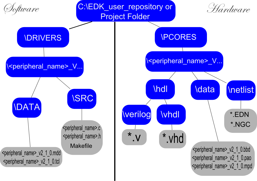
The hardware directory structure is as follows: the peripheral folder sits in the \pcores folder for an EDK repository or a project repository. Naming is key for everything here. For the peripherals main directory, the name of the top-level verilog or VHDL file must be used. If this peripheral has multiple versions, the user may append a _vX_XX_B, where the X’s are version numbers and B is the version letter. Beneath this directory there typically sit 3 or 4 folders: “data,” “hdl,” “netlist,” and sometimes “devl,” which is less important.
\devl
The “devl” directory is a sometimes auto-generated directory that contains a project-navigator version of the peripheral for debugging purposes. The folder is not utilized in XPS.
\netlist
The “netlist” directory is only required when black-box netlist files are used in place of HDL for certain modules. An example is the FIFO-generator in coregent. It will output NGC/EDN files which must be placed in the “netlist” directory if the FIFO is to be used as a sub-module for your peripheral.
\hdl
The “hdl” directory contains two sub-folders: one for verilog files and the other for vhdl files. All of the peripheral’s hdl files go into their respective folders based on extension-type. It should be noted that XPS allows for mixed-HDL peripherals. Secondarily, as stated early, it’s very important to use the peripherals top-level HDL files for naming the peripherals master directory and corresponding data files.
\data
The “data” directory contains a *.pao file, a *.mpd file, and sometimes a *.bbd file, which stand for “Peripheral Analysis Order,” “Microprocessor Peripheral Description,” and “Black Box Definition,” respectively. All of these files must have the same name of the top-level verilog file appended with “_v2_1_0” for use in EDK8. For example, the radio controller’s data files are named, “radio_controller_v2_1_0.mpd” and “radio_controller_v2_1_0.pao.”
The PAO file
The “pao” file is a list of all the verilog/vhdl files that appear in the peripheral and what library they belong to. Technically, if the reader is coding all of this by hand, the only library present will most likely be the top-level. The general format is as follows:
lib <peripheral_name>_vX_XX_B <file/module-name> verilog/vhdl
Typically it’s good practice to list the modules in hierarchal order, but generating may still work so long as just the top-level module is listed last. Here is “radio_controller_v2_1_0.pao” as an example:
lib proc_common_v2_00_a proc_common_pkg vhdl
lib proc_common_v2_00_a family vhdl
lib proc_common_v2_00_a or_muxcy vhdl
lib proc_common_v2_00_a or_gate vhdl
lib proc_common_v2_00_a counter_bit vhdl
lib proc_common_v2_00_a counter vhdl
lib proc_common_v2_00_a inferred_lut4 vhdl
lib proc_common_v2_00_a srl_fifo2 vhdl
lib proc_common_v2_00_a pf_counter_bit vhdl
lib proc_common_v2_00_a pf_counter vhdl
lib proc_common_v2_00_a pf_counter_top vhdl
lib proc_common_v2_00_a pf_occ_counter vhdl
lib proc_common_v2_00_a pf_occ_counter_top vhdl
lib proc_common_v2_00_a pf_adder_bit vhdl
lib proc_common_v2_00_a pf_adder vhdl
lib proc_common_v2_00_a pf_dpram_select vhdl
lib proc_common_v2_00_a srl16_fifo vhdl
lib proc_common_v2_00_a pselect vhdl
lib proc_common_v2_00_a valid_be vhdl
lib proc_common_v2_00_a ld_arith_reg vhdl
lib proc_common_v2_00_a mux_onehot vhdl
lib proc_common_v2_00_a down_counter vhdl
lib proc_common_v2_00_a ipif_pkg vhdl
lib proc_common_v2_00_a ipif_steer vhdl
lib proc_common_v2_00_a direct_path_cntr_ai vhdl
lib interrupt_control_v1_00_a interrupt_control vhdl
lib wrpfifo_v1_01_b pf_dly1_mux vhdl
lib wrpfifo_v1_01_b ipif_control_wr vhdl
lib wrpfifo_v1_01_b wrpfifo_dp_cntl vhdl
lib wrpfifo_v1_01_b wrpfifo_top vhdl
lib rdpfifo_v1_01_b ipif_control_rd vhdl
lib rdpfifo_v1_01_b rdpfifo_dp_cntl vhdl
lib rdpfifo_v1_01_b rdpfifo_top vhdl
lib opb_ipif_v3_01_c reset_mir vhdl
lib opb_ipif_v3_01_c brst_addr_cntr vhdl
lib opb_ipif_v3_01_c opb_flex_addr_cntr vhdl
lib opb_ipif_v3_01_c brst_addr_cntr_reg vhdl
lib opb_ipif_v3_01_c opb_be_gen vhdl
lib opb_ipif_v3_01_c srl_fifo3 vhdl
lib opb_ipif_v3_01_c write_buffer vhdl
lib opb_ipif_v3_01_c opb_bam vhdl
lib opb_ipif_v3_01_c opb_ipif vhdl
lib radio_controller_v1_03_a user_logic verilog
lib radio_controller_v1_03_a spi_top verilog
lib radio_controller_v1_03_a spi_shift verilog
lib radio_controller_v1_03_a spi_clgen verilog
lib radio_controller_v1_03_a spi_defines verilog
lib radio_controller_v1_03_a timescale verilog
lib radio_controller_v1_03_a radio_controller vhdl
This particular example contains other EDK libraries that were auto-generated from XPS. Auto-generation processes will be discussed in later sections.
The MPD file
The “mpd” file is the most important file XPS uses for the peripheral. This file firstly lists synthesis/peripheral options used by XPS, bus-interface definitions and parameters if used, and all of the top-level ports. The file may also contain code used for *.xbd integration. Here is “radio_controller_v2_1_0.mpd” as an example:
###################################################################
##
## Name     : radio_controller
## Desc     : Microprocessor Peripheral Description
##          : Automatically generated by PsfUtility
##
###################################################################

BEGIN radio_controller

## Peripheral Options
OPTION IPTYPE = PERIPHERAL
OPTION IMP_NETLIST = TRUE
OPTION CORE_STATE = ACTIVE
OPTION IP_GROUP = MICROBLAZE:PPC:USER
OPTION USAGE_LEVEL = BASE_USER
OPTION HDL = MIXED

#OPTION IPTYPE = PERIPHERAL
#OPTION IMP_NETLIST = TRUE
#OPTION HDL = MIXED
#OPTION IP_GROUP = MICROBLAZE:PPC:USER
#OPTION CORE_STATE = DEVELOPMENT
#OPTION USAGE_LEVEL = BASE_USER

IO_INTERFACE IO_IF = radio_controller, IO_TYPE = WARP_RADIOCONTROLLER_V1


## Bus Interfaces
BUS_INTERFACE BUS = SOPB, BUS_TYPE = SLAVE, BUS_STD = OPB

## Generics for VHDL or Parameters for Verilog
PARAMETER C_BASEADDR = 0xffffffff, DT = std_logic_vector, MIN_SIZE = 0x100, BUS = SOPB, ADDRESS = BASE, PAIR = C_HIGHADDR
PARAMETER C_HIGHADDR = 0x00000000, DT = std_logic_vector, BUS = SOPB, ADDRESS = HIGH, PAIR = C_BASEADDR
PARAMETER C_OPB_AWIDTH = 32, DT = INTEGER, BUS = SOPB
PARAMETER C_OPB_DWIDTH = 32, DT = INTEGER, BUS = SOPB
PARAMETER C_FAMILY = virtex2p, DT = STRING

## Ports
PORT OPB_Clk = "", DIR = I, SIGIS = Clk, BUS = SOPB
PORT OPB_Rst = OPB_Rst, DIR = I, SIGIS = Rst, BUS = SOPB
PORT Sl_DBus = Sl_DBus, DIR = O, VEC = [0:(C_OPB_DWIDTH-1)], BUS = SOPB
PORT Sl_errAck = Sl_errAck, DIR = O, BUS = SOPB
PORT Sl_retry = Sl_retry, DIR = O, BUS = SOPB
PORT Sl_toutSup = Sl_toutSup, DIR = O, BUS = SOPB
PORT Sl_xferAck = Sl_xferAck, DIR = O, BUS = SOPB
PORT OPB_ABus = OPB_ABus, DIR = I, VEC = [0:(C_OPB_AWIDTH-1)], BUS = SOPB
PORT OPB_BE = OPB_BE, DIR = I, VEC = [0:((C_OPB_DWIDTH/8)-1)], BUS = SOPB
PORT OPB_DBus = OPB_DBus, DIR = I, VEC = [0:(C_OPB_DWIDTH-1)], BUS = SOPB
PORT OPB_RNW = OPB_RNW, DIR = I, BUS = SOPB
PORT OPB_select = OPB_select, DIR = I, BUS = SOPB
PORT OPB_seqAddr = OPB_seqAddr, DIR = I, BUS = SOPB

PORT spi_clk = "", DIR = O
PORT data_out = "", DIR = O
PORT radio1_cs = "", DIR = O
PORT radio2_cs = "", DIR = O
PORT radio3_cs = "", DIR = O
PORT radio4_cs = "", DIR = O
PORT dac1_cs = "", DIR = O
PORT dac2_cs = "", DIR = O
PORT dac3_cs = "", DIR = O
PORT dac4_cs = "", DIR = O
PORT radio1_SHDN = "", DIR = O
PORT radio1_TxEn = "", DIR = O
PORT radio1_RxEn = "", DIR = O
PORT radio1_RxHP = "", DIR = O
PORT radio1_LD = "", DIR = I
PORT radio1_24PA = "", DIR = O
PORT radio1_5PA = "", DIR = O
PORT radio1_ANTSW = "", DIR = O, VEC = [0:1], IO_IS = radio1_antsw
PORT radio1_LED = "", DIR = O, VEC = [0:2], IO_IS = radio1_LED
PORT radio1_ADC_RX_DCS = "", DIR = O
PORT radio1_ADC_RX_DFS = "", DIR = O
PORT radio1_ADC_RX_OTRA = "", DIR = I
PORT radio1_ADC_RX_OTRB = "", DIR = I
PORT radio1_ADC_RX_PWDNA = "", DIR = O
PORT radio1_ADC_RX_PWDNB = "", DIR = O
PORT radio1_DIPSW = "", DIR = I, VEC = [0:3], IO_IS = radio1_dipsw
PORT radio1_RSSI_ADC_CLAMP = "", DIR = O
PORT radio1_RSSI_ADC_HIZ = "", DIR = O
PORT radio1_RSSI_ADC_OTR = "", DIR = I
PORT radio1_RSSI_ADC_SLEEP = "", DIR = O
PORT radio1_RSSI_ADC_D = "", DIR = I, VEC = [0:9], IO_IS = radio1_rssi_ADC_D
PORT radio1_TX_DAC_PLL_LOCK = "", DIR = I
PORT radio1_TX_DAC_RESET = "", DIR = O
PORT radio1_RxHP_external = "", DIR = I
PORT radio2_SHDN = "", DIR = O
PORT radio2_TxEn = "", DIR = O
PORT radio2_RxEn = "", DIR = O
PORT radio2_RxHP = "", DIR = O
PORT radio2_LD = "", DIR = I
PORT radio2_24PA = "", DIR = O
PORT radio2_5PA = "", DIR = O
PORT radio2_ANTSW = "", DIR = O, VEC = [0:1], IO_IS = radio2_antsw
PORT radio2_LED = "", DIR = O, VEC = [0:2], IO_IS = radio2_LED
PORT radio2_ADC_RX_DCS = "", DIR = O
PORT radio2_ADC_RX_DFS = "", DIR = O
PORT radio2_ADC_RX_OTRA = "", DIR = I
PORT radio2_ADC_RX_OTRB = "", DIR = I
PORT radio2_ADC_RX_PWDNA = "", DIR = O
PORT radio2_ADC_RX_PWDNB = "", DIR = O
PORT radio2_DIPSW = "", DIR = I, VEC = [0:3], IO_IS = radio2_dipsw
PORT radio2_RSSI_ADC_CLAMP = "", DIR = O
PORT radio2_RSSI_ADC_HIZ = "", DIR = O
PORT radio2_RSSI_ADC_OTR = "", DIR = I
PORT radio2_RSSI_ADC_SLEEP = "", DIR = O
PORT radio2_RSSI_ADC_D = "", DIR = I, VEC = [0:9], IO_IS = radio2_rssi_ADC_D
PORT radio2_TX_DAC_PLL_LOCK = "", DIR = I
PORT radio2_TX_DAC_RESET = "", DIR = O
PORT radio2_RxHP_external = "", DIR = I
PORT radio3_SHDN = "", DIR = O
PORT radio3_TxEn = "", DIR = O
PORT radio3_RxEn = "", DIR = O
PORT radio3_RxHP = "", DIR = O
PORT radio3_LD = "", DIR = I
PORT radio3_24PA = "", DIR = O
PORT radio3_5PA = "", DIR = O
PORT radio3_ANTSW = "", DIR = O, VEC = [0:1], IO_IS = radio3_antsw
PORT radio3_LED = "", DIR = O, VEC = [0:2], IO_IS = radio3_LED
PORT radio3_ADC_RX_DCS = "", DIR = O
PORT radio3_ADC_RX_DFS = "", DIR = O
PORT radio3_ADC_RX_OTRA = "", DIR = I
PORT radio3_ADC_RX_OTRB = "", DIR = I
PORT radio3_ADC_RX_PWDNA = "", DIR = O
PORT radio3_ADC_RX_PWDNB = "", DIR = O
PORT radio3_DIPSW = "", DIR = I, VEC = [0:3], IO_IS = radio3_dipsw
PORT radio3_RSSI_ADC_CLAMP = "", DIR = O
PORT radio3_RSSI_ADC_HIZ = "", DIR = O
PORT radio3_RSSI_ADC_OTR = "", DIR = I
PORT radio3_RSSI_ADC_SLEEP = "", DIR = O
PORT radio3_RSSI_ADC_D = "", DIR = I, VEC = [0:9], IO_IS = radio3_rssi_ADC_D
PORT radio3_TX_DAC_PLL_LOCK = "", DIR = I
PORT radio3_TX_DAC_RESET = "", DIR = O
PORT radio3_RxHP_external = "", DIR = I
PORT radio4_SHDN = "", DIR = O
PORT radio4_TxEn = "", DIR = O
PORT radio4_RxEn = "", DIR = O
PORT radio4_RxHP = "", DIR = O
PORT radio4_LD = "", DIR = I
PORT radio4_24PA = "", DIR = O
PORT radio4_5PA = "", DIR = O
PORT radio4_ANTSW = "", DIR = O, VEC = [0:1], IO_IS = radio4_antsw
PORT radio4_LED = "", DIR = O, VEC = [0:2], IO_IS = radio4_LED
PORT radio4_ADC_RX_DCS = "", DIR = O
PORT radio4_ADC_RX_DFS = "", DIR = O
PORT radio4_ADC_RX_OTRA = "", DIR = I
PORT radio4_ADC_RX_OTRB = "", DIR = I
PORT radio4_ADC_RX_PWDNA = "", DIR = O
PORT radio4_ADC_RX_PWDNB = "", DIR = O
PORT radio4_DIPSW = "", DIR = I, VEC = [0:3], IO_IS = radio4_dipsw
PORT radio4_RSSI_ADC_CLAMP = "", DIR = O
PORT radio4_RSSI_ADC_HIZ = "", DIR = O
PORT radio4_RSSI_ADC_OTR = "", DIR = I
PORT radio4_RSSI_ADC_SLEEP = "", DIR = O
PORT radio4_RSSI_ADC_D = "", DIR = I, VEC = [0:9], IO_IS = radio4_rssi_ADC_D
PORT radio4_TX_DAC_PLL_LOCK = "", DIR = I
PORT radio4_TX_DAC_RESET = "", DIR = O
PORT radio4_RxHP_external = "", DIR = I

END
Aside from the top-level ports and XBD information, almost all of this code was auto-generated by XPS. The IO_INTERFACE IO_IF = radio_controller, IO_TYPE = WARP_RADIOCONTROLLER_V1 and IO_IS =” ” are used for interfacing the peripheral with the XBD file. If netlists are used in the peripheral, in which this example they aren’t, “OPTION RUN_NGCBUILD = TRUE” must be added to the option’s section.
The BBD file
Finally, the “bbd” file, is simply a list of all netlist files that have been included with the project. Here is an example for a FIFO that was built in CoreGenerator:
FILES
################################################################################
xmit_buffer_fifo.edn, xmit_buffer_fifo_fifo_generator_v2_1_as_1.ngc, xmit_buffer_fifo_fifo_generator_v2_1_as_1_blkmemdp_v6_2_xst.edn
More information on the proper formatting for all of these filetypes may be found in: EDK/doc/psf_rm.pdf
The Software-Side
At this point, the provided information is all that a HDL-proficient user should need to create a non-powerPC controlled peripheral in XPS. Implementing PowerPC control is not an easy task to accomplish by hand – as the PowerPC controls peripherals via a built-in BUS interface. XPS provides easy methods for accomplishing this through automatically generating templates that a user’s hdl can be inserted under.
In the “drivers” directory for the EDK repository or project, the peripheral’s driver folder will sit. It must use the same exact name as it’s counterpart in the "pcores" directory (top-level hdl name with version information appended if necessary). Within this folder, there sits the “data” and “src” directory.
\src
The “src” directory contains the peripherals associated C-code files and a file called “Makefile.”
\data
The “data” directory contains two files: “<peripheral_name>_v2_1_0.mdd” and “<peripheral_name>_v2_1_0.tcl.”
All three of these files (the Makefile, MDD, and TCL) contain information XPS uses to essentially connect the drivers with hardware during bitstream generation
Provided below are examples of each of these three files, but it is strongly suggested that the user allows XPS to generate these files automatically as will be described in later sections of this guide. THIS GUIDE WILL NOT EXPLAIN HOW TO BUILD POWER-PC-CONTROLLABLE PERIPHERALS BY HAND.
“radio_controller_v2_1_0.mdd”
OPTION psf_version = 2.1.0;

BEGIN DRIVER radio_controller

  OPTION supported_peripherals = (radio_controller);
  OPTION depends = (common_v1_00_a);
  OPTION copyfiles = all;

END DRIVER
“radio_controller_v2_1_0.tcl”
#uses "xillib.tcl"

proc generate {drv_handle} {
  xdefine_include_file $drv_handle "xparameters.h" "radio_controller" "NUM_INSTANCES" "DEVICE_ID" "C_BASEADDR" "C_HIGHADDR"
}
“Makefile”
COMPILER=
ARCHIVER=
CP=cp
COMPILER_FLAGS=
EXTRA_COMPILER_FLAGS=
LIB=libxil.a

RELEASEDIR=../../../lib
INCLUDEDIR=../../../include
INCLUDES=-I./. -I${INCLUDEDIR}

INCLUDEFILES=*.h
LIBSOURCES=*.c
OUTS = *.o

libs:
	echo "Compiling radio_controller"
	$(COMPILER) $(COMPILER_FLAGS) $(EXTRA_COMPILER_FLAGS) $(INCLUDES) $(LIBSOURCES)
	$(ARCHIVER) -r ${RELEASEDIR}/${LIB} ${OUTS}
	make clean

include:
	${CP} $(INCLUDEFILES) $(INCLUDEDIR)

clean:
	rm -rf ${OUTS}
| | HOME | | NEXT: Creating Peripherals That do NOT Require PowerPC Control |
Attachments (1)
- periph_hierarchy.png (144.2 KB) - added by snovich 18 years ago.
Download all attachments as: .zip