IFS Calibration and Benchmarks
Honoring the interframe spacings (IFS) of 802.11 is fundamental to the interaction of different 802.11 devices in a shared wireless medium. For this reason, we have thoroughly calibrated and characterized the IFS values of the 802.11 Reference Design. For a comparison baseline, we have also characterized a Linksys WRT54GL running the Tomato firmware.
Short Interframe Space (SIFS)
The SIFS defines the gap in time between:
- A data frame and its corresponding ACK
- An RTS and CTS
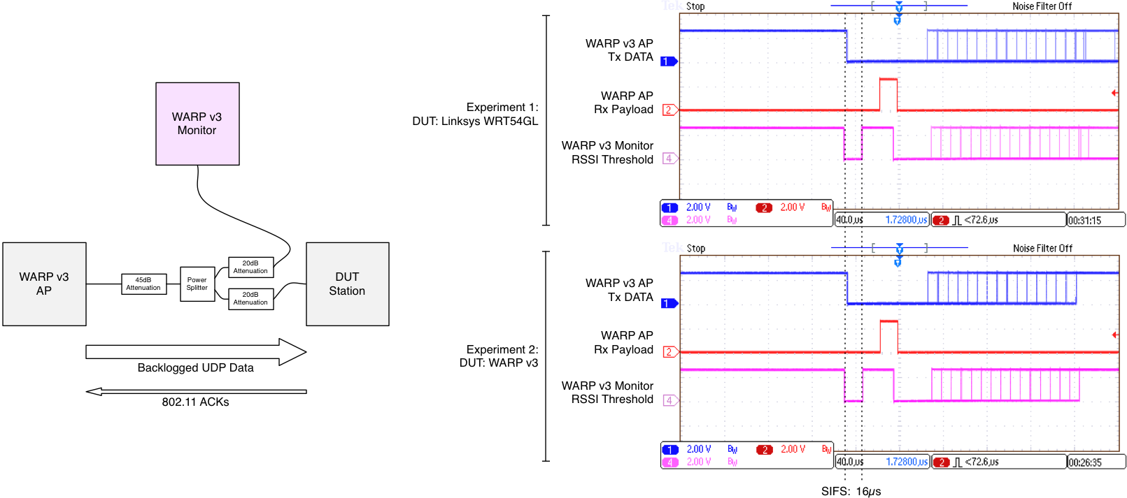
The 802.11 standard defines this gap in time from the perspective of a third party observing the medium -- it is the idle period between the last sample of energy from one packet to the first sample of energy to the next. To test our implementation's understanding of the SIFS interval, we have constructed an experiment using RF cabling, an RF power splitter, and RF attenuators. A WARP AP sends a data packet to the device under test (DUT) and the DUT is responsible for sending an ACK of that packet. A second WARP node, called the "monitor," observes the transaction and outputs a signal to an oscilloscope that corresponds to RSSI crossing a threshold. This signal basically shows whether the medium is busy or idle.

|
| Comparison of SIFS interval with commercial 802.11 device |
The above figure shows the monitor's thresholded RSSI signal in addition to signals from the perspective of the WARP AP that correspond to the PHY's start of TX processing and RX processing. The 802.11 Reference Design implementation adheres to the standard's specification of a SIFS interval of 16µs.
DCF Interframe Space (DIFS) and Slot
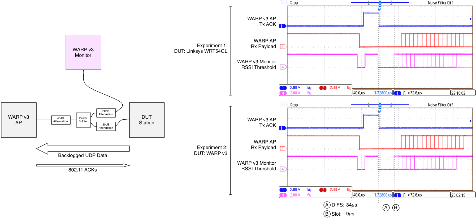
Two other critical interframe spacings are the DCF Interframe Space (DIFS) and slot time. The DIFS corresponds to the minimum amount of time between busy medium event and the transmission of another frame (excluding the cases covered by SIFS). The slot time corresponds to the amount of time between two different contention window (CW) values. To test our implementation's understanding these intervals, we have reversed the flow of traffic relative to the SIFS test above. Here, the DUT generates a data frame and the WARP AP is responsible for sending an ACK for that packet. In the case that the DUT chooses a CW of zero, the observed gap in time where the medium is idle corresponds to a DIFS. By increasing persistence on the oscilloscope to view multiple transmissions, other intervals corresponding to nonzero CW values can be observed. Comparing the relative start times of these other transmissions allows us to measure the slot time.

|
| Comparison of DIFS interval and slot time with commercial 802.11 device |
The above figure shows that the 802.11 Reference Design implementation adheres to the standard's specification of a slot interval of 9µs. Furthermore, it shows that the implementation adheres to a DIFS interval of 34µs (SIFS + 2*slot time = 16µs + 2*9µs = 34µs).