CM-MMCX User Guide: External I/O
The CM-MMCX clock module routes external clock signals to MMCX connectors. There are four connectors on the module:
| Connector | Signal | WARP v3 Connection |
|---|---|---|
| RF Ref Out | RF reference clock output | RF ref clock buffer (U20) CLKOUT0 |
| RF Ref In | RF reference clock Input | RF ref clock buffer (U20) CLKIN2 |
| Samp Out | Sampling clock output | Sampling clock buffer (U46) CLKOUT1 |
| Samp In | Sampling clock Input | Sampling clock buffer (U46) CLKIN2 |
The frequency of each clock signal will depend on the configuration of the corresponding clock buffer on the host WARP v3 board. Refer to the WARP v3 Clocking user guide for details.
Connectors
The MMCX connectors are standard-polarity, standard-gender 50-ohm MMCX connectors.
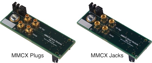
The CM-MMCX PCB can be assembled with either MMCX jacks or MMCX plugs, illustrated in the figure below. For connections between WARP v3 kits we recommend CM-MMCX modules with MMCX jacks, which will allow use of readily available cable assemblies with MMCX plugs (like Digi-Key J731-ND).
