802.11 Reference Design
- Download
- Changelog
- FAQ
- Architecture
Using the Design...
Benchmarks
- IFS Calibration
- Throughput
- Transmitter Characterization
- Receiver Characterization
- Pkt. Det. Min. Power Characterization
MAC
Upper-level
Lower-level...
- PHY
Experiments Framework...
- Packet Flow
- FPGA Architecture
- FPGA Resource Usage
- App Notes
- Other Resources
- License
- Changelog
Ethernet Encapsulation and De-encapsulation
Ethernet encapsulation describes the process by which an 802.11 MPDU wraps a full Ethernet frame for transmission while Ethernet de-encapsulation describes the reverse. The 802.11-2012 standard describes this process in Annex P, "the Integration Function." The process is slightly different depending whether the device performing the action is an access point or station.
Access Point

|
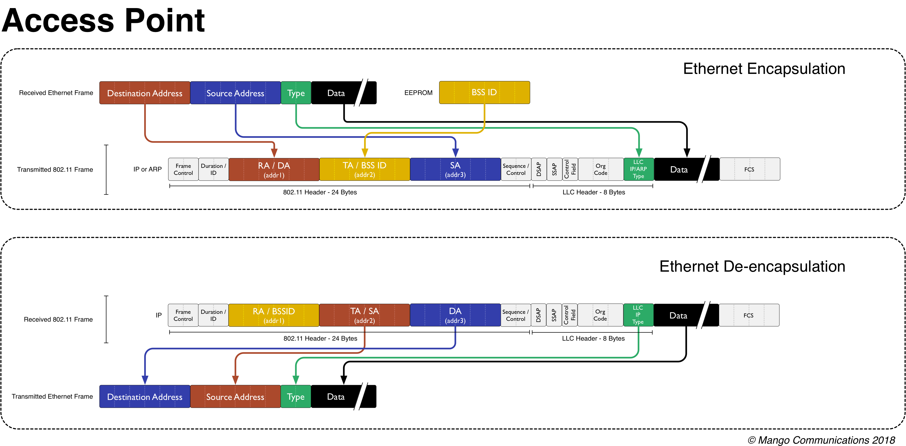
| AP Encapsulation and De-encapsulation |
The above figure shows how an AP encapsulates and de-encapsulates different types of Ethernet frames.
Encapsulation
When an AP encapsulates a packet, it treats the destination address in that Ethernet frame as the receiver address (addr1) in the outgoing wireless MPDU. The source address of the Ethernet frame, however, is not the transmitter address (addr2) of the outgoing wireless MPDU -- the TA address must be the wireless MAC address (or BSSID) of the AP. Instead, the source address of the Ethernet frame is put into the third address location (addr3) of the outgoing 802.11 header.
De-encapsulation
De-encapsulation at the AP recognizes that a station must include the BSSID of the AP as the first argument of the 802.11 header. This receiver address (addr1) is not the destination address of the Ethernet frame. Instead, the destination address is included in the third address location (addr3) of the incoming 802.11 header. The transmitter address (addr2) is the source address of the Ethernet frame that should be generated.
Station

|
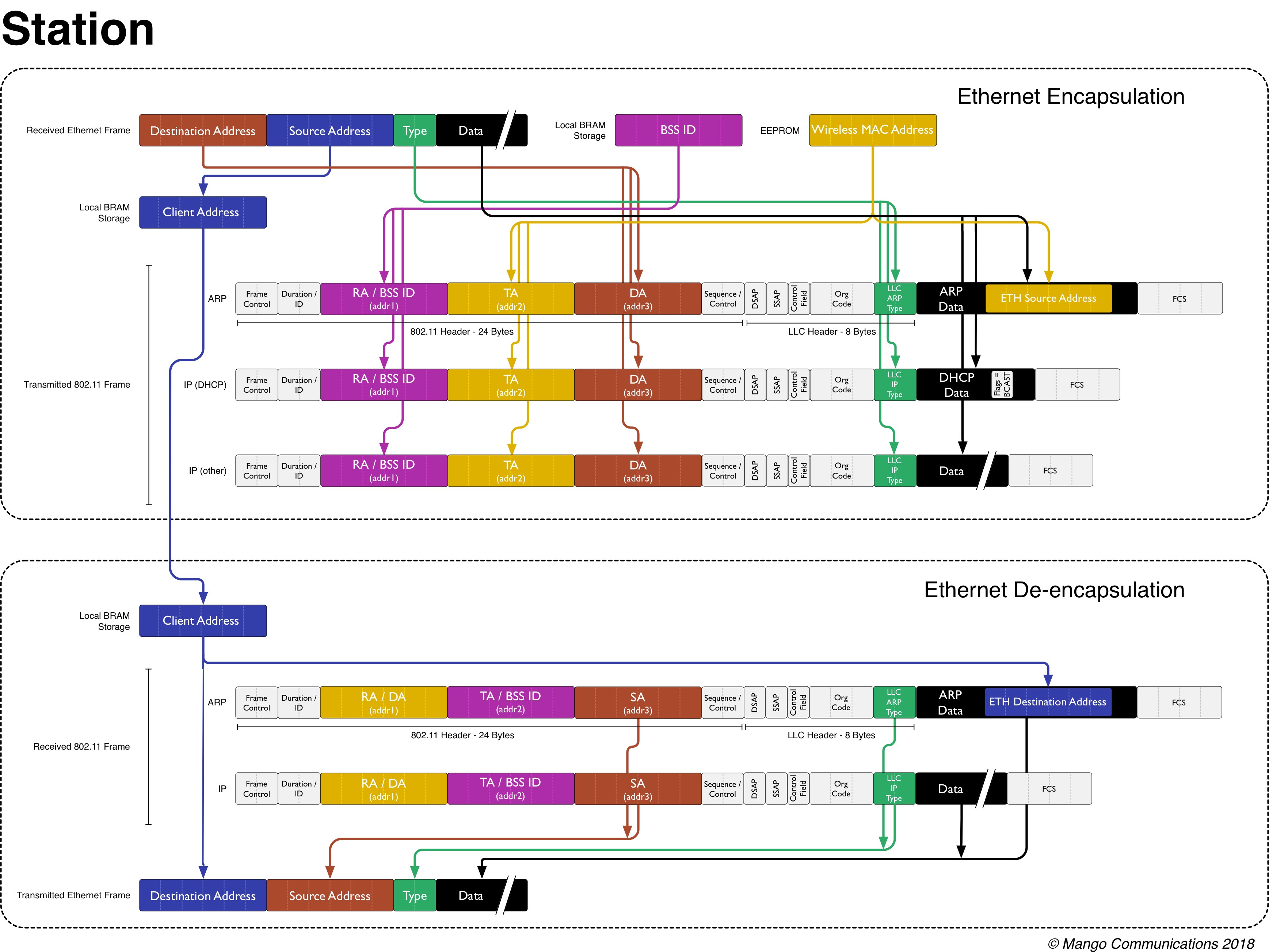
| STA Encapsulation and De-encapsulation |
The above figure shows how a STA encapsulates and de-encapsulates different types of Ethernet frames. In general, the process is very similar to that of the AP's but is complicated by the addition of an extra hardware MAC address: the address of the client device connected to the WARP STA via Ethernet. The STA implementation must spoof all packets to "trick" the rest of the network into thinking that the Ethernet source address of the connected client is the wireless MAC address of the WARP STA.
Encapsulation
The transmitter address (addr) of all outgoing MPDUs must be the MAC address of the WARP STA -- otherwise, the AP will not accept these packets since the Ethernet address of the client device was not used during the authentication and association handshake. As such, the source address of all received Ethernet frames does not appear anywhere in the outgoing wireless MPDU transmission. Since this address will be needed to construct Ethernet transmissions, we save this address into memory. Note: This approach has a limitation that only one device should be plugged into the Ethernet port of the WARP STA. The implementation cannot handle seeing multiple source MAC addresses without implementing NAT.
In addition to the standard address Ethernet to MPDU address translation, the STA must also modify the contents of a few specific types of packets:
- ARP: ARP requests contain the Ethernet source address within the packet itself in a addition to its usual place at the front of the Ethernet header. The 802.11 STA implementation spoofs this address with the wireless MAC address of the WARP node.
- DHCP: DHCP discovery and request packets can contain a flag that ensures that the DHCP handshake takes place via broadcast MAC addresses rather than unicast MAC addresses that the DHCP server learns. When in unicast mode, outgoing DHCP packets from the AP may be addressed to the client device connected to the 802.11 STA rather than the wireless address of the 802.11 STA -- this confuses the AP since the client address is not in the list of associated devices. By raising the broadcast flag in DHCP packets, the WARP STA can ensure that the packets pass through the wireless network unimpeded.
De-encapsulation
The de-encapsulation process has the added step of needing to undo the spoofing that took place during the encapsulation process. From the address stored previously in memory, the 802.11 STA overwrites the outgoing destination address as well as the address stored internally to ARP packets before transmitting the packet via Ethernet.
IBSS Node

|
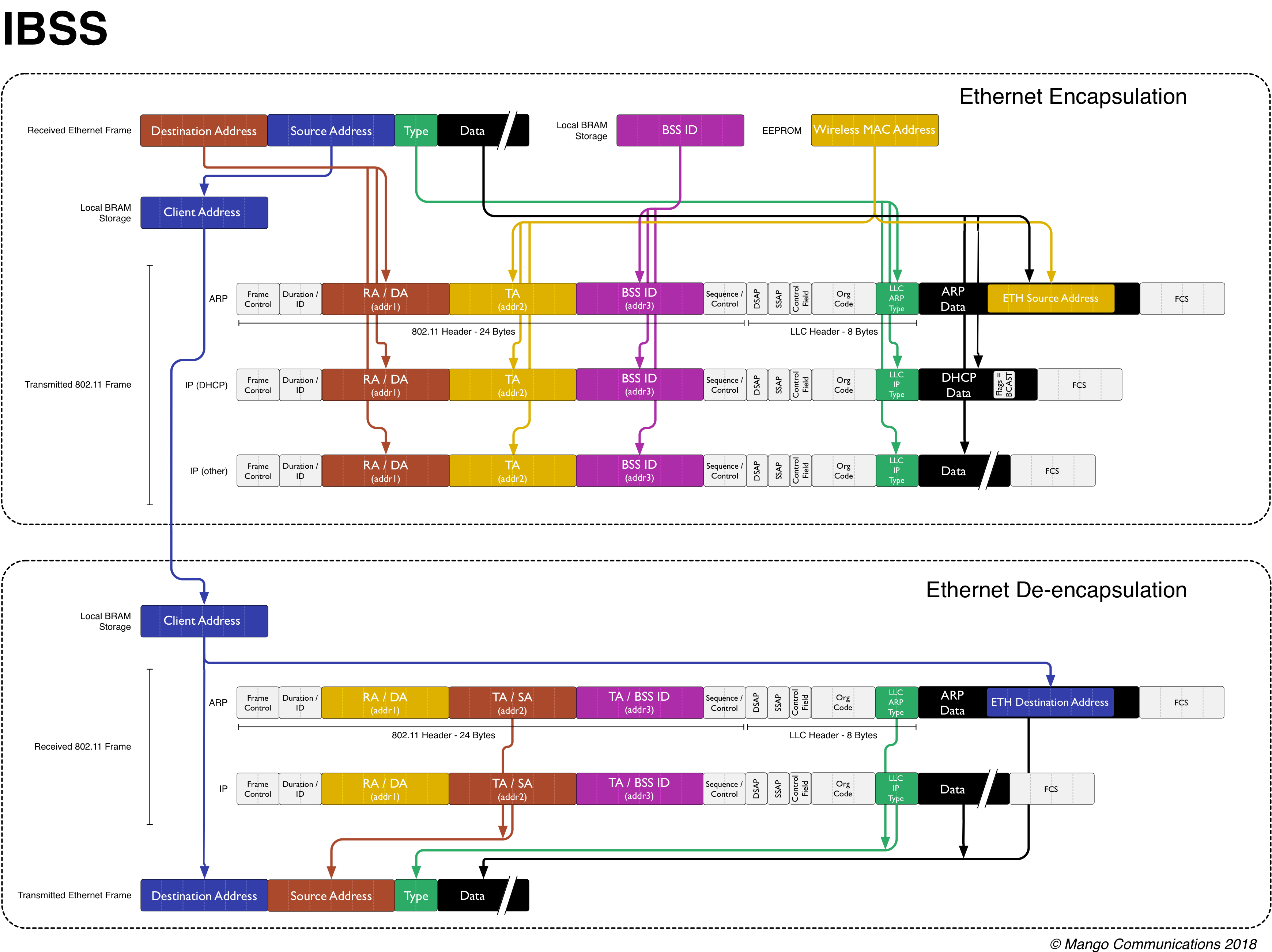
| IBSS Node Encapsulation and De-encapsulation |
The above figure shows how an IBSS node encapsulates and de-encapsulates different types of Ethernet frames. An IBSS node has the same challenge as a traditional STA -- it must spoof the MAC address of whatever Ethernet client is attached to it.
Encapsulation
The encapsulation behavior is nearly identical to the STA. The only difference is that the Ethernet destination addresses is directly used as the RA (addr1). In an IBSS, traffic is not sent via an AP. It is addressed directly.
De-encapsulation
De-encapsulation is also nearly identical to the STA. Since the RA (addr1) contains the destination of the wireless frame, that address is used as the destination address of the outgoing Ethernet frame.