| Version 16 (modified by murphpo, 10 years ago) (diff) |
|---|
802.11 Reference Design: Packet Flow
As packets move through the 802.11 reference design, the packet contents must be accessible by CPU High, CPU Low and the PHY cores. The design achieves this using the interconnects illustrated in the figure blow.

Each MicroBlaze has access to two AXI interconnects. For both CPUs the MicroBlaze DP port (non-cached peripheral memory access port) is connected to an AXI4 Lite interconnect. The peripheral cores connected to each AXI4 Lite interconnect are accessible by only one CPU. The cores are divided between CPUs based on which part of the MAC needs to access them. For example the radio_controller, w3_ad_controller and PHY configuration registers are all attached to the interconnect for CPU Low. Similarly the Ethernet cores are attached to the peripheral bus for CPU High. The mailbox and mutex ports for each CPU are also attached to their corresponding peripheral busses.
The MicroBlaze DC (cached memory access port) for both CPUs are attached to a shared AXI4 interconnect. The data cache is disabled in the Reference Design; all memory access via the DC ports access a slave memory device via the AXI4 interconnect. Both CPU DC ports are masters on this interconnect. The primary slave devices on this interconnect are the block RAMs used to implement the packet buffers (discussed below). Both CPUs can read and write any location in both memories. The AXI4 interconnect is a 64-bit crossbar clocked at 160MHz, which provides sufficient throughput to avoid contention between the CPUs.
Packet Buffers
The 802.11 Reference Design uses two dual-port 32KB RAMs as Tx and Rx packet buffers. One port of each RAM is attached to a BRAM interface controller (axi_bram_ctrl), which maps the RAM onto the address space of the two CPUs. The other port of each RAM is attached directly to the corresponding PHY core. These direct PHY connections do not traverse an AXI interconnect. Instead both PHY cores (Tx and Rx) implement native 64-bit BRAM interfaces in logic.
The PHY cores divide each 32KB BRAM into 8 4KB buffers. The PHY numbers these buffers [0:7]. The low-level MAC code provides the packet buffer index to the PHY for each Tx and Rx event.
Tx Packet Flow
The flow of packets leading to wireless transmissions are illustrated below. All wireless transmissions pass through the upper-level MAC framework's Tx queuing system. The framework individually dequeues packets and copies them to a PHY packet buffer for processing and transmission by the lower-level MAC.

There are three sources of transmit packets in the 802.11 Reference Design:
- Ethernet Rx: data packets received on the ETH A interface may be encapsulated and enqueued for transmission if the address and packet types match filters implemented in the upper-level MAC code.
- Local: the upper-level MAC application can generate traffic internally. This includes management frames (beacons, probe request/response, etc) and arbitrary traffic generated by the framework's LTG system.
- Wireless Rx: packets received from the wireless interface can be enqueued for transmission. This path is used by the AP to relay packets from one associated STA to another.
Rx Packet Flow
The flow of packets received wirelessly is illustrated below. All wireless receptions are written to a receive packet buffer by the PHY. The lower-level MAC evaluates the received packet and may pass it up to the upper-level MAC for additional processing.

Received packets passed up to the upper-level MAC are routed to one of three sinks:
- Ethernet Tx: data packets may be de-encapsulated and transmitted via the ETH A interface
- Local: the upper-level MAC may directly consume a received packet. This includes management frames and arbitrary traffic generated by the LTG system at another node.
- Wireless Tx: as explained above, some MAC applications may re-transmit received packets via the wireless interface
Packet Buffer Contents
Each 4KB packet buffer is used to store packet payloads and related metadata. The MAC can store arbitrary metadata in each packet buffer before the actual packet bytes. The PHY must be configured with the size of the metadata so it knows where to read (Tx) and write (Rx) packet payloads. This is done from wlan_mac_low.c:
//Move the PHY's starting address into the packet buffers by PHY_XX_PKT_BUF_PHY_HDR_OFFSET.
//This accounts for the metadata located at the front of every packet buffer (Xx_mpdu_info)
wlan_phy_rx_pkt_buf_phy_hdr_offset(PHY_RX_PKT_BUF_PHY_HDR_OFFSET);
wlan_phy_tx_pkt_buf_phy_hdr_offset(PHY_TX_PKT_BUF_PHY_HDR_OFFSET);
The PHY_RX_PKT_BUF_PHY_HDR_OFFSET constat is defined as PHY_TX_PKT_BUF_PHY_HDR_SIZE + PHY_RX_PKT_BUF_PHY_HDR_OFFSET, where PHY_RX_PKT_BUF_PHY_HDR_SIZE is 8 (for the PHY header) and PHY_TX_PKT_BUF_PHY_HDR_SIZE is sizeof(rx_frame_info).
Similarly PHY_TX_PKT_BUF_PHY_HDR_OFFSET is defined as PHY_TX_PKT_BUF_PHY_HDR_SIZE + PHY_TX_PKT_BUF_PHY_HDR_OFFSET.
The Tx and Rx packet buffer contents for the reference design are described below.
Tx Pkt Buffers The struct definitions for tx_frame_info are below. These structs are defined in wlan_mac_misc_util.h.
typedef struct{
    u8      rate;           ///< PHY rate index
    u8      antenna_mode;   ///< Tx antenna selection
    s8      power;          ///< Tx power (in dBm)
    u8      flags;          ///< Flags affecting waveform construction
} phy_tx_params; //4 bytes

typedef struct{
    u8      num_tx_max;     ///< Maximum number of transmission attempts
    u8      flags;          ///< Flags affecting waveform construction
    u8      reserved[2];
} mac_tx_params; //4 bytes

typedef struct{
    phy_tx_params phy; ///< PHY Tx params
    mac_tx_params mac; ///< Lower-level MAC Tx params
} tx_params; //8 bytes

typedef struct{
    u64 timestamp_create;   ///< MAC timestamp of packet creation
    u32 delay_accept;       ///< Time in microseconds between timestamp_create and packet acceptance by CPU Low
    u32 delay_done;         ///< Time in microseconds between acceptance and transmit completion
    u64 unique_seq;         ///< Unique sequence number for this packet (12 LSB used as 802.11 MAC sequence number)
    u8 state;               ///< Packet buffer state - TX_MPDU_STATE_EMPTY, TX_MPDU_STATE_TX_PENDING or TX_MPDU_STATE_READY
    u8 tx_result;           ///< Result of transmission attempt - TX_MPDU_RESULT_SUCCESS or TX_MPDU_RESULT_FAILURE
    u8 QID;                 ///< Queue ID from which this packet was taken
    u8 num_tx;              ///< Number of actual PHY transmissions of this packet, including all re-transmissions
    u8 flags;               ///< Bit flags en/disabling certain operations by the lower-level MAC
    u8 padding1[3];
    u16 length;             ///< Number of bytes in MAC packet, including MAC header and FCS
    u16 AID;                ///< Association ID of the node to which this packet is addressed
    u8 padding2[4];
    tx_params params;       ///< Additional lower-level MAC and PHY parameters
} tx_frame_info; 48 bytes
The MAC must write the packet payload immediately after the tx_frame_info, starting with the SIGNAL field. The lower-level MAC code should use the wlan_phy_set_tx_signal(pkt_buf, rate, length) macro to write the SIGNAL field to the appropriate offset.
Rx Pkt Buffers The struct definition for rx_frame_info are below. This struct is defined in wlan_mac_misc_util.h.
The channel_est field reserves space for the channel estimates generated by the Rx PHY during reception. The PHY writes the estimates directly to the Rx packet buffer. The offset for writing channel estimates is set via the wlan_phy_rx_pkt_buf_h_est_offset(offset) macro.
typedef struct{
    u8 state;           ///< Packet buffer state - RX_MPDU_STATE_EMPTY, RX_MPDU_STATE_RX_PENDING, RX_MPDU_STATE_FCS_GOOD or RX_MPDU_STATE_FCS_BAD
    u8 rate;            ///< PHY rate index
    u16 length;         ///< Number of bytes in MAC packet, including MAC header and FCS
    s8 rx_power;        ///< Rx power, in dBm
    u8 rf_gain;         ///< Gain setting of radio Rx LNA, in [0,1,2]
    u8 bb_gain;         ///< Gain setting of radio Rx VGA, in [0,1,...31]
    u8 channel;         ///< Channel index
    u8 flags;           ///< Bit flags
    u8 ant_mode;        ///< Rx antenna selection
    u8 reserved[2];
    u32 additional_info;///< Field to hold MAC-specific info, such as a pointer to a station_info
    u64 timestamp;      ///< MAC timestamp at time of reception
    u32 channel_est[64];///< Rx PHY channel estimates
} rx_frame_info;
The PHY begins writing received bytes immediately after the rx_frame_info. The received SIGNAL and SERVICE fields are written to the first 5 bytes following the rx_frame_info. The PHY then skips 3 bytes and writes the next received byte (the first byte of the MAC header) to 8 bytes past the rx_frame_info. This convention aligns received payloads to a 64-bit boundary, easing access by the MAC software and DMAs. Generally the MAC software ignores the SIGNAL and SERVICE fields in the Rx packet buffer, instead relying on the rate/length values provided by the MAC core.
Tx Ping-Pong Buffers
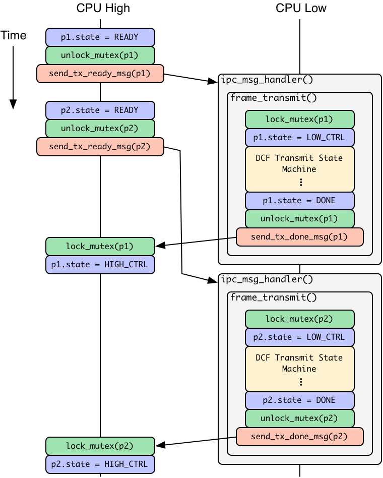
The lower-level MAC and PHY process a single Tx packet at any given time. While a packet is being transmitted the upper-level MAC prepares the next packet for transmission. Two buffers from the Tx packet buffer RAM are used for this ping-pong approach.
The handshake between the upper and lower level MACs to initiate new packet transmissions is illustrated below. The handshake uses three IPC messages:
- IPC_MBOX_TX_MPDU_READY(pkt_buf_index): indication from CPU High that the packet in pkt_buf_index is ready for transmission
- IPC_MBOX_TX_MPDU_ACCEPT(pkt_buf_index): indication from CPU Low that the packet in pkt_buf_index is currently being transmitted by the lower-level MAC and PHY. This message always follows the corresponding IPC_MBOX_TX_MPDU_READY and precedes the corresponding IPC_MBOX_TX_MPDU_DONE. The upper-level MAC may safely ignore this message if desired.
- IPC_MBOX_TX_MPDU_DONE(pkt_buf_index): indication from CPU Low that transmission of the packet in pkt_buf_index is complete.
It is critical that CPU High not modify the contents of any packet buffer for which it has sent IPC_MBOX_TX_MPDU_READY until it receives the corresponding IPC_MBOX_TX_MPDU_DONE message. Likewise CPU Low must only modify packet buffers for which it as received IPC_MBOX_TX_MPDU_READY and only before it sends IPC_MBOX_TX_MPDU_DONE.

The upper-level MAC framework calls application-specific callback functions upon receipt of IPC_MBOX_TX_MPDU_ACCEPT and IPC_MBOX_TX_MPDU_DONE messages. The MAC application can use these callbacks to manage internal state, create log entries, update statistics, etc.
Attachments (1)
- tx_pkt_buf_pingpong_impl.png (122.3 KB) - added by murphpo 8 years ago.
Download all attachments as: .zip